
Related Manuals for YOKOGAWA CA500


Summary of Contents for YOKOGAWA CA500
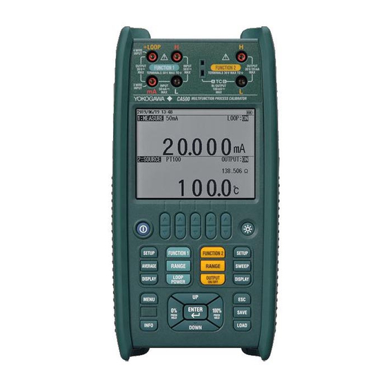
- Page 1 User’s Manual CA500, CA550 Multifunction Process Calibrator IM CA500-01EN 1st Edition...
- Page 2 Thank you for purchasing the CA500/CA550 Multifunction Process Calibrator. This user’s manual explains the features, operating procedures, and handling precautions of the CA500 and CA550. To ensure correct use, please read this manual thoroughly before operation. After reading this manual, keep it in a safe place. The following manuals, including this one, are provided as manuals for the CA500 and CA550.
- Page 3 Revisions • October, 2019 1st Edition IM CA500-01EN...
-
Page 4: Conventions Used In This Manual
Calls attention to actions or conditions that could cause light injury to the user or damage to the instrument or user’s data, and precautions that can be taken to prevent such occurrences. Note Calls attention to information that is important for the proper operation of the instrument. IM CA500-01EN... -
Page 5: How To Read This Manual
HART communication signals or BRAIN communication signals superimposed in the transmission line. Set this to off when communication signals are not superimposed in the transmission line. IM CA500-01EN In addition, “arrow keys” and “cursor keys” indicate the following keys. Arrow keys... -
Page 6: Table Of Contents
Source Function ......................1-2 Sweep function ....................... 1-8 Measurement Function ....................1-12 Calibration Function for Field Instruments ..............1-17 Saving and Loading CA500 Data ................. 1-18 Saving and Loading CA550 Data ................. 1-20 Other Features ......................1-24 Chapter 2 Source DC Voltage Source ...................... - Page 7 Formatting (Initializing) the Internal Memory ..............6-8 Chapter 7 USB Function USB Interface Features and Specifications ..............7-1 Connecting through the USB Interface ................7-2 List of Commands ......................7-3 Commands ........................7-5 Error Codes ........................7-19 Status Byte Format ...................... 7-20 Index IM CA500-01EN...
-
Page 8: Chapter 1 Features
OUTPUT 250Ω +LOOP DC/DC Display FUNCTION 2 part USB B TC-A +TC-A Power AMP TC-A Reference voltage source OUTPUT Setting DC/DC Excess volatge / excess Power current protection source DC/DC Current detection control Current voltage BATT. conversion -TC-A IM CA500-01EN... -
Page 9: Source Function
Percentage and source value Percentage 1-5 V source value Square root output (1-5V√) 1.0000 V 1.0000 V 2.0000 V 1.2500 V 3.0000 V 2.0000 V 4.0000 V 3.2500 V 100% 5.0000 V 5.0000 V IM CA500-01EN... - Page 10 20.000 mA 20.000 mA Simulate (20 mA Simulate) Function You can connect this instrument to a distributor and simulate a two-wire transmitter. This is valid when the range is set to 4-20 mA Simulate. CA500/CA550 Distributor 4-20mA — IM CA500-01EN...
- Page 11 Because the source resistance is calibrated without including the voltage drop of the leaked cables, the lead cable resistance will result in error. • To source the resistance accurately, use of the three-wire system or four-wire system. Calibration target (three-wire CA500/CA550 measuring instrument) L’ Black IM CA500-01EN...
- Page 12 RJ sensor. Calibrating only the thermometer Calibrating including the thermocouple Calibration target CA500/CA550 CA500/CA550 Calibration target External RJ sensor Thermocouple Thermocouple Internal RJ sensor...
- Page 13 If the contact output is set on during frequency output, a contact signal can be output with the specified frequency or number of pulses. The instrument’s Input terminal of the output terminal output destination device 0.5 to 30 VDC IM CA500-01EN...
- Page 14 Source value (°C) Source value (resistance ) — Frequency Source value Percentage — — Percentage Source value — — The source value or percentage shown in the main display area can also be changed directly using arrow keys. IM CA500-01EN...
-
Page 15: Sweep Function
The time period during which the source value is varied. You can set the rise time and fall time separately. Interval Time The time period during which the source value is held when the source value reaches 0% or 100% after sweeping. IM CA500-01EN... - Page 16 100% 100% Index Same slope DOWN key UP key (DOWN key) Sweep start (UP key) Sweep start Output on (OUTPUT key) Output on (OUTPUT key) If you press OUTPUT while sweeping is in progress, the source turns off. IM CA500-01EN...
- Page 17 Saving Data After sweeping, source values, measure values, and other data can be saved to files. For details, see section 1.6, “Saving and Loading CA500 Data”, or section 1.7, “Saving and Loading CA550 Data”. 1-10...
- Page 18 The time period during which each source value is held. Source Number You can assign source values to each number from 1 to 10 on the CA500 and 1 to 20 on the CA550. When the output is turned on, the specified source values are generated in order from source number 1.
-
Page 19: Measurement Function
Input resistance: 10 Ω or less Loop Power A loop test can be performed by applying a constant voltage of 24 VDC to a two-wire transmitter and measuring the transfer signal. — Distributor 4-20mA Two-wire transmitter 24VDC CA500/CA550 1-12 IM CA500-01EN... - Page 20 0.0°C to +1395.0°C ASTM E1751/E1751M PR20-40 0.0°C to +1888.0°C ASTM E1751/E1751M Complies also with JIS C 1602 The setting can be changed to comply with IPTS-68 (JIS C 1602 1981). Temperature Scale This instrument complies with ITS-90 and IPTS-68. 1-13 IM CA500-01EN...
- Page 21 RTD and the instrument the same, measurements can be made without hardly being affected by the resistance of the lead cables. Four-wire system: Measurements can be made without being affected by the resistance in the lead wires connecting the RTD and the instrument. 1-14 IM CA500-01EN...
- Page 22 The CA550 calculates the error in the actual output value relative to the output value (specified according to the specifications of the device to be calibrated) that is mapped to the source value. Furthermore, this instrument calculates the measurement value percentages relative to the specified 0% value and 100% value. 1-15 IM CA500-01EN...
- Page 23 Measured value Measured value (voltage) Temperature monitor (°C) (reference junction temperature) Measured value Percentage Measured value — (°C) (resistance) Percentage Measured value Measured value — (°C) (resistance) Frequency Measured value Percentage — — Percentage Measured value — — 1-16 IM CA500-01EN...
-
Page 24: Calibration Function For Field Instruments
Moreover, the instrument indicates pass or fail depending on whether the measured value is within the tolerance set in advance. You can view the errors and pass/fail judgments in the files saved automatically by the program sweep function. 1-17 IM CA500-01EN... -
Page 25: Saving And Loading Ca500 Data
Saving and Loading CA500 Data For details on the CA550, see section 1.7. Saving Data The following three methods are available to save data. • Save data by pressing the SAVE key • Save data automatically after the completion of a step sweep •... - Page 26 1.6 Saving and Loading CA500 Data Function2 Information Saved Data Notes Source value Function Range 0% value 100% value Sweep setting* Interval time Repeat Saving Data ON/OFF Temperature Thermocouple terminal TC-A/TC-B setting TC-B RJC setting ON/OFF Burnout setting ON/OFF TC scale standard setting IPTS-68/ITS-90 Temperature unit °C...
-
Page 27: Saving And Loading Ca550 Data
Saving and Loading CA550 Data For details on the CA500, see section 1.6. Saving Data The following three methods are available to save data. • Save data by pressing the SAVE key • Save data automatically after the completion of a step sweep •... - Page 28 TC scale standard setting. 0: ITS-90, 1:IPTS-68 Temperature unit. 0: °C FREQUENCY SETTING Amplitude voltage setting (frequency setting) Pulse count setting Number DATE Measurement date YYYY/MM/DD TIME Measurement time hh:mm:ss Index MEASURE Measured value SOURCE Source value 1-21 IM CA500-01EN...
- Page 29 Burnout setting. 0: OFF, 1:ON TC scale standard setting. 0: ITS-90, 1:IPTS-68 Temperature unit. 0: °C FREQUENCY SETTING Amplitude voltage setting (frequency setting) Pulse count setting Number DATE Measurement date YYYY/MM/DD TIME Measurement time hh:mm:ss MEASURE Measured value SOURCE Source value 1-22 IM CA500-01EN...
- Page 30 Folder Structure The following figure shows the CA550 folder structure. Root SaveData Data saved with the SAVE key is saved. Measurement/source data (.csv) of step SweepData sweeps is saved. Measurement/source data (.csv) of program CalibrationData sweeps is saved. 1-23 IM CA500-01EN...
-
Page 31: Other Features
You can use dedicated communication commands to remotely control the instrument from a PC. The following operations can be controlled remotely. • CA500/CA550 configuration (limited features) • CA500/CA550 configuration retrieval (limited features) • Measured data retrieval USB Mass Storage (CA550) You can use the instrument as a PC’s USB mass storage device. - Page 32 The format type is quick format (logical format). Instrument Information You can view the model (CA500/CA550), serial number, firmware version, and most recent inspection date or calibration date. A simple wiring diagram is displayed according to the Function 1 and Function 2 settings.
-
Page 33: Chapter 2 Source
When the source range is 1-5V or 1-5V√, press UP or DOWN to change the source value. Divided Source See section 2.8, “Dividing and Generating the Source Values”. Sourcing with the Sweep Function See section 2.9, “Sweep Source”. IM CA500-01EN... - Page 34 Source value = (25/100)×(25/100)×(5 V - 1 V) + 1 V = 1.25 V. Notes about Sourcing Be careful not to short the output terminals. When the output terminals are shorted, the output is automatically turned off by the protection function. IM CA500-01EN...
-
Page 35: Dc Current Source
When the source range is 4-20mA, 4-20mA√ or 4-20mA Simulate, press UP or DOWN to change the source value. Divided Source See section 2.8, “Dividing and Generating the Source Values”. Sourcing with the Sweep Function See section 2.9, “Sweep Source”. IM CA500-01EN... - Page 36 Source value = (25/100)×(25/100)×(20 mA - 4 mA) + 4 mA = 5 mA. Notes about Sourcing Be careful not to open the output terminals. When the output terminals are opened, the output is automatically turned off by the protection function. IM CA500-01EN...
-
Page 37: Resistance Source
The source value set in step five is output, and OUTPUT:OFF on the screen changes to OUTPUT:ON. To turn off the source, press OUTPUT ON/OFF again. Divided Source See section 2.8, “Dividing and Generating the Source Values”. Sourcing with the Sweep Function See section 2.9, “Sweep Source”. IM CA500-01EN... - Page 38 You can select from the following two source ranges. Range Source Range 400 Ω 0.00 Ω ~ 440.00 Ω 4000 Ω 0.0 Ω ~ 4400.0 Ω Note If the allowable measurement current exceeds the upper limit, the source value display blinks. IM CA500-01EN...
-
Page 39: Voltage Source Corresponding To Tc Thermoelectromotive Force
Select Temperature Setup, and press ENTER. A Temperature Setup setup screen appears. Set the terminal. Set the RJC sensor. Turn burnout on or off. (measurement setting see section 3.4) Set the temperature scale. Select TC Terminal. TC-A and TC-B appear in the selection menu. IM CA500-01EN... - Page 40 The source value set in step five is output, and OUTPUT:OFF on the screen changes to OUTPUT:ON. To turn off the source, press OUTPUT ON/OFF again. Divided Source See section 2.8, “Dividing and Generating the Source Values”. Sourcing with the Sweep Function See section 2.9, “Sweep Source”. IM CA500-01EN...
- Page 41 If you perform a temperature measurement or temperature source using an RJC immediately after using loop power or simulating 20 mA, the measured value or source value may be affected by the temperature rise inside the instrument. Wait for the temperature inside instrument to stabilize before using it. IM CA500-01EN...
-
Page 42: Resistance Source Corresponding To The Rtd Temperature
The source value set in step five is output, and OUTPUT:OFF on the screen changes to OUTPUT:ON. To turn off the source, press OUTPUT ON/OFF again. Divided Source See section 2.8, “Dividing and Generating the Source Values”. Sourcing with the Sweep Function See section 2.9, “Sweep Source”. 2-10 IM CA500-01EN... - Page 43 -200.0°C to 630.0°C Cu50M -180.0°C to 200.0°C Cu100M -180.0°C to 200.0°C Match the RTD type of this instrument to that of the measuring instrument. Note If the excitation current exceeds the upper limit, the source value display blinks. Index 2-11 IM CA500-01EN...
-
Page 44: Frequency And Pulse Source
Use the arrow keys to set the source range. The display returns to the source and measurement value display. Setting the Source Value With the source value and measurement value displayed, use the arrow keys to set the source value. Source range Source value 2-12 IM CA500-01EN... - Page 45 Select Frequency Setup, and press ENTER. A Frequency Setup setup screen appears. Turn the contact output on or off. Select Contact Output. ON and OFF appear in the selection menu. Use the arrow keys to set the contact output to ON or OFF. To generate contact signals, select 2-13 IM CA500-01EN...
- Page 46 The source value set in step 5 is output. The signal is generated according to the specified pulse count. To turn off the source, press OUTPUT ON/OFF again. Divided Source See section 2.8, “Dividing and Generating the Source Values”. 2-14 IM CA500-01EN...
-
Page 47: Duty Cycle
Be careful not to apply a voltage exceeding 30 VDC to the source terminal of this instrument. The instrument’s Input terminal of the output terminal output destination device 0.5 to 30 VDC When you turn on the contact output, the amplitude setting is ignored. 2-15 IM CA500-01EN... -
Page 48: Setting The 0% And 100% Values
Press the arrow key corresponding to EXIT SETUP. The settings are confirmed, and a screen appears showing the source value and measurement value. The cancel the settings, press ESC to return to the screen in step 2. To initialize the settings, press the arrow key corresponding to INIT SETUP. 2-16 IM CA500-01EN... - Page 49 0% or 100% value is generated. To turn off the source, press OUTPUT ON/OFF again. Description 0% and 100% Values Set the values within each source range. These values become the divided source range or sweep source range. Index 2-17 IM CA500-01EN...
-
Page 50: Dividing And Generating The Source Values
Increasing or Decreasing the Source Value Press UP or DOWN. The source value increases or decreases by the specified division width. Note You can change the source value to the 0% or 100% value by pressing the 0% or 100% key. 2-18 IM CA500-01EN... - Page 51 When you use the step sweep function, the source value of each step can be held for the same time period, and the source value can be stepped up or down automatically (see “Step Sweep” in section 2.9, “Sweep Source”). 2-19 IM CA500-01EN...
-
Page 52: Sweep Source
Press the arrow key corresponding to EXIT SETUP. The settings are confirmed, and a screen appears showing the source value and measurement value. The cancel the settings, press ESC to return to the screen and step 2. To initialize the settings, pressing the arrow key corresponding to INIT SETUP. 2-20 IM CA500-01EN... -
Page 53: Index
The number of steps is determined by the number of divisions of the divided source (see section 2.8, “Dividing and Generating the Source Values”). Turning Repeat On and Off Select Repeat. ON and OFF appear in the selection menu. Use the arrow keys to set the sweep repetition to ON or OFF. 2-21 IM CA500-01EN... - Page 54 When you press DOWN, the 100% source values displayed, and sweeping starts from 100% to If repeat is set to OFF, sweeping stops automatically after one cycle is executed. Press OUTPUT ON/OFF to turn off the source. If repeat is set to ON, sweeping continues until you turn off the source. 2-22 IM CA500-01EN...
- Page 55 2.9 Sweep Source Setting and Executing Program Sweeps (CA500) Select Program Sweep Setup, and press ENTER. CA500 Set the interval time. Turn data save on or off. Setting the Interval Time Select Interval Time, and press ENTER. A list of options appears.
- Page 56 The source values are generated in order from No. 1 according to the settings. When the last specified number is reached, the instrument returns to No. 1 and continues the signal generation. To stop a sweep, press OUTPUT ON/OFF. 2-24 IM CA500-01EN...
- Page 57 Use the cursor keys to select characters, and then press ENTER. Press the arrow key corresponding to DONE to confirm the entered character string. For details on the alphanumeric input window, see chapter 3, “Common Operations,” Getting Started Guide (IM CA500-02EN). Likewise, set information for Serial Number, Tag Number, and Loop Number. 2-25...
- Page 58 Press UP or DOWN. The source values are generated in order from No. 1 according to the settings. When the last specified number is reached, sweeping stops automatically. To stop a sweep in progress, press OUTPUT ON/OFF. 2-26 IM CA500-01EN...
- Page 59 0% or 100% value after the change. If you select ON, sweeping continues until the source is turned off with the OUTPUT ON/OFF key. 2-27 IM CA500-01EN...
- Page 60 The source value and measurement value of each step are automatically saved. The maximum number of data values that can be saved on the CA500 is 100. The maximum number of data values that can be saved in a single file on the CA550 is 2000, the maximum number of files that can be saved is 250.
- Page 61 Assigned source values in the 0% to 100% range are generated in order by number for a given time period. You can assign up to 10 source values on the CA500 and 20 source values on the CA550. Source number...
- Page 62 Operation While Sweeping Is in Progress Pressing any of the following keys while sweeping stops the sweeping. FUNCTION2, RANGE2, ESC, or OUTPUT Pressing any other keys except the power key does not affect the sweeping operation. Some keys are disabled during sweeping. 2-30 IM CA500-01EN...
-
Page 63: Chapter 3 Measurement
Use the arrow keys to set the measurement range. The display returns to the source and measurement value display. Index Setting the 0% and 100% Values (when necessary) Set the 0% and 100% values according to section 3.7, “Setting the 0% and 100% Values”. IM CA500-01EN... - Page 64 Assign an output value (specified according to the specifications of the device to be calibrated) to the 0% or 100% measurement value of this instrument, which is mapped to the 0% or 100% source value of this instrument. The instrument displays errors, pass/fail judgment results (CA550), measurement percentages relative to the assigned value. IM CA500-01EN...
-
Page 65: Dc Current Measurement
Set the 0% and 100% values according to section 3.7, “Setting the 0% and 100% Values”. Loop Power Source (when performing loop tests) Press LOOP POWER. LOOP on the screen is turned on, and the instrument generates a 24 VDC loop power. To stop the source, press LOOP POWER again. IM CA500-01EN... - Page 66 Loop power can be generated during DC current measurement. Transfer signals can be measured while supplying a constant voltage of 24 VDC to the two-wire transmitter. The two-wire transmitter and distributor are not connected. — Distributor 4-20mA Two-wire transmitter 24 VDC CA500/CA550 IM CA500-01EN...
-
Page 67: Resistance Measurement
Press the arrow key corresponding to EXIT SETUP. The settings are confirmed, and the screen reverts to show the source value and measurement value. The cancel the settings, press ESC to return to the screen and step 6. To initialize the settings, pressing the arrow key corresponding to INIT SETUP. IM CA500-01EN... - Page 68 You can select from the following two measurement ranges. Range Measurement Range 400Ω 0.00 Ω ~ 440.00 Ω 4000Ω 0.0 Ω ~ 4400.0 Ω Wiring Systems You can select from 2W (two-wire), 3W (three-wire), and 4W (four-wire). This setting is shared with the RTD. IM CA500-01EN...
-
Page 69: Temperature Measurement Using Thermocouples
Select TC Terminal. TC-A and TC-B appear in the selection menu. Using the arrow keys, select TC-A to use the TC-A terminal (thermocouple mini plug) or TC-B to use TC-B. To finish entering the settings here, proceed to step 16. IM CA500-01EN... - Page 70 -200.0°C to +600.0°C -20.0°C to +1767.0°C -20.0°C to +1768.0°C +600.0°C to +1820.0°C 0.0°C to +2315.0°C -200.0°C to +800.0°C 0.0°C to +2500.0°C D (W3Re/W25Re) 0.0°C to +2315.0°C G (W/W26Re) +100.0°C to +2315.0°C PLATINEL II 00.0°C to +1395.0°C PR20-40 0.0°C to +1888.0°C IM CA500-01EN...
- Page 71 If you perform a temperature measurement or temperature source using an RJC immediately after using loop power or simulating 20 mA, the measured value or source value may be affected by the temperature rise inside the instrument. Wait for the temperature inside instrument to stabilize before using it. IM CA500-01EN...
-
Page 72: Temperature Measurement Using Rtds
Press the arrow key corresponding to EXIT SETUP. The settings are confirmed, and the screen reverts to show the source value and measurement value. The cancel the settings, press ESC to return to the screen and step 6. To initialize the settings, pressing the arrow key corresponding to INIT SETUP. 3-10 IM CA500-01EN... - Page 73 PT50G -200.0°C to 800.0°C PT100G -200.0°C to 630.0°C Cu50M -180.0°C to 200.0°C Cu100M -180.0°C to 200.0°C Wiring Systems You can select from 2W (two-wire), 3W (three-wire), and 4W (four-wire). This setting is shared with resistance measurement. Index 3-11 IM CA500-01EN...
-
Page 74: Frequency And Pulse Measurement
Use the arrow keys to select the measurement time, and then press ENTER. You can set the measurement range to 1 minute to 60 minutes in steps of number 1 minute. 3-12 IM CA500-01EN... - Page 75 When the measurement signal frequency is low, it may take some time before the measurement result is displayed. During this time, the screen displays “- - - - -.” If the frequency is outside the measurement range, “OL” is displayed. 3-13 IM CA500-01EN...
-
Page 76: Setting The 0% And 100% Values
Press the arrow key corresponding to EXIT SETUP. The settings are confirmed, and the screen reverts to show the source value and measurement value. The cancel the settings, press ESC to return to the screen and step 1. To initialize the settings, pressing the arrow key corresponding to INIT SETUP. 3-14 IM CA500-01EN... - Page 77 0% or 100% measurement value of this instrument, which is mapped to the 0% or 100% source Index value of this instrument. The instrument displays errors, pass/fail judgment results (CA550), measurement percentages relative to the assigned value. 3-15 IM CA500-01EN...
-
Page 78: Setting The Tolerance (Ca550)
(the input value to the device to be calibrated). The pass/fail judgment result is recorded in the file saved by the CA550 program sweep. For details on saving program sweeps, see section 5.2, “Saving Sweeps.” 3-16 IM CA500-01EN... -
Page 79: Average Value Display
The average, maximum, and minimum values are displayed on the FUNCTION 1 screen. Maximum Minimum Average Description Moving average values for every five measured values and the maximum value (MAX) and minimum value (MIN) of the moving average values are displayed. Index 3-17 IM CA500-01EN... -
Page 80: Chapter 4 Calibrating Field Instruments (Ca550)
If further adjustment is necessary, perform readjustment and calibration again. By comparing the calibration data before adjustment and calibration data after adjustment, you can maintain the continuity in the measurement values of the field instrument. IM CA500-01EN... -
Page 81: Setting Calibration Conditions
Use the arrow keys to set the function of your choice. The display returns to the source and measurement value display. Under Function 1, press RANGE. Use the arrow keys to set the measurement range. The display returns to the source and measurement value display. IM CA500-01EN... - Page 82 Press the arrow key corresponding to EXIT SETUP. The settings are confirmed, and a screen appears showing the source value and measurement value. The cancel the settings, press ESC to return to the screen and step 2. To initialize the settings, pressing the arrow key corresponding to INIT SETUP. IM CA500-01EN...
- Page 83 Judging Measurement Values Measurement results are judged pass or fail depending on whether the measurement values are within the tolerance. Judgment results are saved along with the tolerance and the differences between the measurement values and reference values. IM CA500-01EN...
-
Page 84: Saving Calibration Results
• If the operating system of the PC connected to this instrument is Windows 8.1, you need to install a CDC system definition file for YOKOGAWA products in the PC. For details on how to obtain the system definition file, access the following YOKOGAWA’s webpage, and download the file. -
Page 85: Chapter 5 Saving Data
SAVED is pressed. Description The method to save data is different between the CA500 and CA550. CA500 You can save the date and time, the selected function, range, measurement value, and source value when SAVE is pressed. - Page 86 YYYYMMDDhhmmss: year, month, day, hour, minute, and second when the first data entry was saved YYYY: year, MM: month, DD: day, hh: hour, mm: minute, ss: second xx: A sequence number starting from 00 that is assigned when the save date and time overlaps IM CA500-01EN...
- Page 87 Burnout setting. 0: OFF, 1:ON TC scale standard setting. 0: ITS-90, 1:IPTS-68 Temperature unit. 0: °C FREQUENCY SETTING Amplitude voltage setting (frequency setting) Pulse count setting Number DATE Measurement date YYYY/MM/DD TIME Measurement time hh:mm:ss MEASURE Measurement value SOURCE Source value Index IM CA500-01EN...
-
Page 88: Saving Sweeps
Depending on the number-of-steps setting, 100 data entries may be exceeded when a sweep is saved. In this situation, an error message is displayed when a sweep is started. Data is saved in a dedicated format of this instrument. If you abort a sweep, the data up to that point is saved. IM CA500-01EN... - Page 89 Burnout setting. 0: OFF, 1:ON TC scale standard setting. 0: ITS-90, 1:IPTS-68 Temperature unit. 0: °C FREQUENCY SETTING Amplitude voltage setting (frequency setting) Pulse count setting Number DATE Measurement date YYYY/MM/DD TIME Measurement time hh:mm:ss MEASURE Measurement value SOURCE Source value IM CA500-01EN...
- Page 90 Proper judgment cannot be made unless the 0% or 100% measurement value of this instrument is assigned to the output value (specified according to the specification of the device to be calibrated) that is mapped to the 0% or 100% source value of this instrument. IM CA500-01EN...
-
Page 91: Loading And Deleting Saved Data
With the source value and measurement value displayed, press LOAD. A list of saved data is displayed. On the CA500, a list of data saved using the SAVE key is displayed. On the CA550, a list of CSV files saved using program sweeps is displayed. - Page 92 Data saved on the CA500 or data saved automatically using the CA550 program sweep can be deleted on the ROAD screen. To delete other types of data, format the internal memory.
-
Page 93: Copying Saved Data To A Pc (Ca550)
CalibrationData sweeps is saved. Note • Data cannot be written to or deleted from the CA500 internal memory from a PC. Index • The CA550 internal memory information displayed on the PC is not updated automatically. To update the information, remove the USB cable, or restart the CA550. -
Page 94: Saved Data Format (Ca550)
±xx.xxx xxxx/xx/xx xx:xx:xx ±xxx.xx ±xx.xxx xxxx/xx/xx xx:xx:xx ±xxx.xx ±xx.xxx xxxx/xx/xx xx:xx:xx ±xxx.xx ±xx.xxx xxxx/xx/xx xx:xx:xx ±xxx.xx ±xx.xxx xxxx/xx/xx xx:xx:xx ±xxx.xx ±xx.xxx xxxx/xx/xx xx:xx:xx ±xxx.xx ±xx.xxx xxxx/xx/xx xx:xx:xx ±xxx.xx ±xx.xxx xxxx/xx/xx xx:xx:xx ±xxx.xx ±xx.xxx xxxx/xx/xx xx:xx:xx ±xxx.xx ±xx.xxx 5-10 IM CA500-01EN... - Page 95 ±xxx.xx ±xx.xxx ±xxx.xx FAIL xxxx/xx/xx xx:xx:xx ±xxx.xx ±xx.xxx ±xxx.xx PASS xxxx/xx/xx xx:xx:xx ±xxx.xx ±xx.xxx ±xxx.xx PASS xxxx/xx/xx xx:xx:xx ±xxx.xx ±xx.xxx ±xxx.xx PASS Index xxxx/xx/xx xx:xx:xx ±xxx.xx ±xx.xxx ±xxx.xx PASS xxxx/xx/xx xx:xx:xx ±xxx.xx ±xx.xxx ±xxx.xx PASS 5-11 IM CA500-01EN...
-
Page 96: Chapter 6 Other Features
To initialize the settings, pressing the arrow key corresponding to INIT SETUP. Turning the Light On and Off and Adjusting the Brightness Press on the instrument’s front panel. Each time you press the soft key, the setting toggles between ON (dark), bright, and OFF. IM CA500-01EN... - Page 97 If the screen light is turned on in a dark location, white spots may appear on the screen. This is due to the material characteristics of the light guide of the screen and has no effect on the performance of the instrument. IM CA500-01EN...
-
Page 98: Turning Communication Resistance On Or Off
The communication resistance is used to provide amplitude to the HART communication signals or BRAIN communication signals superimposed in the transmission line. Set this to off when communication signals are not superimposed in the transmission line. IM CA500-01EN... -
Page 99: Setting The Priority Power Supply
When batteries and USB power supply are both available for running the instrument, you can select the power supply to prioritize. If either the batteries or USB power supply becomes unavailable, a switch is made to the available power supply. IM CA500-01EN... -
Page 100: Setting The Decimal Symbol And Csv Separator
Set the decimal symbol and CSV separator that are used when saving the data sourced and measured by this instrument. Data can be saved according to the specifications of the software that the data will be used in. IM CA500-01EN... -
Page 101: Setting The Date Display Format
• MM/DD/YYYY: month/day/year (Gregorian) The format is applied to the date and time displayed in the upper left of the screen, the date and time on the LOAD screen, and the date and time saved in CSV files from the CA550. IM CA500-01EN... -
Page 102: Setting The Language
To initialize the settings, pressing the arrow key corresponding to INIT SETUP. Description You can select the language used on the screen from the following: • English (default setting) • Japanese • Chinese (simplified) • Korea • Russian IM CA500-01EN... -
Page 103: Formatting (Initializing) The Internal Memory
If you format the internal memory, all the data saved in the internal memory will be erased. Save the necessary data to a PC or the like before formatting the internal memory. On the CA500, a communication command can be used to load saved data into a PC (see section 7.3, “List of Commands”). -
Page 104: Chapter 7 Usb Function
Electrical and mechanical specifications Complies with USB Rev.1.1 Connector Type B connector (receptacle) Number of ports Power supply Self powered, bus powered PC system requirements A PC running Windows 8.1 or Windows 10 with a standard USB port. Index IM CA500-01EN... -
Page 105: Connecting Through The Usb Interface
If the operating system of the PC connected to this instrument is Windows 8.1, you need to install a CDC system definition file for YOKOGAWA products in the PC. For details on how to obtain the system definition file, access the following YOKOGAWA’s webpage, and download the file. -
Page 106: List Of Commands
Other *IDN? Queries the CA500 or CA550 ID string Queries the calibration date of the CA500 or CA550 Sets or queries the on/off state of the screen light Queries the serial number of the CA500 or CA550 Decreases the mth digit of the source value by 1. - Page 107 Sets or queries the current (DCA) source/SIMULATE commands Starts or stops or queries the measurement Sets or queries the n and m values of the n/m divided output Sets or queries the n/m divided output Queries the battery charge state IM CA500-01EN...
-
Page 108: Commands
Queries Command: Transmission command format Return: Response data format of a command with a response (queries) *IDN? Queries the CA500 or CA550 ID string Command = *IDN?<CRLF> -> Return YOKOGAWA,CA5xx,XXXXXXXXX,a.aa.aaa Parameters Manufacturer: YOKOGAWA Model name:... - Page 109 7.4 Commands Queries the calibration date of the CA500 or CA550 Command = BGD?<CRLF> -> Return = BGDm,yyyymmdd<CRLF> Parameters m = 0: Shipment inspection date 1: Factory calibration date yyyy: Gregorian 4 bytes, mm: month 2 bytes, dd: day 2 bytes Sets or queries the on/off state of the screen light Command = BLm<CRLF>...
- Page 110 4: Detect bit 2 (syntax errors) 8: Detect bit 3 (over-range) 16: Detect bit 4 (24 V loop output error) 32: Detect bit 5 (output errors) (Status byte bits 6 and 7 are fixed.) Default value m = 63 (no masking) IM CA500-01EN...
- Page 111 Sets or queries the value corresponding to 0% of FUNCTION1 Command = MLm<CRLF> -> Answer = MLm<CRLF> Command = ML?<CRLF> -> Return = MLm<CRLF> Parameters m = 0% value The setting range and resolution are the same as the display range of the selected range. IM CA500-01EN...
- Page 112 Sets or queries the FUNCTION1 display Command = MSCm<CRLF> -> Answer = MSCm<CRLF> Command = MSC?<CRLF> -> Return = MSCm<CRLF> Parameters m = 0: Normal measurement display (no sub display) 1: Measurement display (with sub display) 2: Percentage display (with sub display) IM CA500-01EN...
- Page 113 Command = OE<CRLF> -> Return = ERRm<CRLF> Outputs the most recent error. After returning the error, the saved error number is overwritten with “ERR00<CRLF>.” “ERR00<CRLF>” is returned when there is no error. Parameters m = Error code number (See “Error Codes.”) 7-10 IM CA500-01EN...
- Page 114 = - - -.- - - (the decimal place is according to the set range) j = E+0, E+3, E-3, E+6 Supported by the CA500. ERR13 results on the CA550. Queries the external RJ sensor connection status Command = OR<CRLF> -> Return = m<CRLF>...
- Page 115 Command = PUm<CRLF> -> Answer = PUm <CRLF> Command = PU?<CRLF> -> Return = PUm <CRLF> Parameters m = 0: Frequency 1: Bandwidth 2: Pulse count This is valid when the source function is set to PULSE. Otherwise, ERR13 results. 7-12 IM CA500-01EN...
- Page 116 1 Can be set when the PULSE source display is set to frequency (PU0) 2 Can be set when the PULSE source display is set to amplitude (PU1) 3 Can be set when the PULSE source display is set to pulse count (PU2) 7-13 IM CA500-01EN...
- Page 117 = 0: Source stop 1: Source start Sets or queries the pulse count operation state Command = SPm<CRLF> -> Answer = SPm<CRLF> Command = SP?<CRLF> -> Return = SPm<CRLF> Parameters m = 0: Stop 1: Start 7-14 IM CA500-01EN...
- Page 118 2: 50 kHz (10 kHz on the CA150) 3: 50 kHz 4: CPM Sets or queries the FUNCTION2 display Command = SSCm<CRLF> -> Answer = SSCm<CRLF> Command = SSC?<CRLF> -> Return = SSCm<CRLF> Parameters m = 0: Normal management display 1: Percentage display 7-15 IM CA500-01EN...
- Page 119 1: ITS-90 (default value) Increases the mth digit of the source value by 1. Command = UPm<CRLF> -> Answer = UP, OK<CRLF> Parameters m = 1 to 5 (1: least significant digit to 5: most significant digit) 7-16 IM CA500-01EN...
- Page 120 Command = WCm<CRLF> -> Return = WCm<CRLF> Command = WC?<CRLF> -> Return = WCm<CRLF> Parameters m = 0: Two-wire system 1: Three-wire system 2: Four-wire system Initializes the settings of FUNCTION1 and FUNCTION2 Command = YC<CRLF> -> Answer = YC, OK<CRLF> Index 7-17 IM CA500-01EN...
- Page 121 = 0: Source 1: SIMULATE(SINK) On the CA500 and CA550, an error is returned when the function of Function 2 is set to mA and the range is not 20 mA. When m = 1, the instrument does not change the source range to 4-20mA Sim but changes the sign of the source value.
-
Page 122: Error Codes
Err 23 Detected an overvoltage or overcurrent in the source output Err 60 Inappropriate setting information saved in EEPROM Err 61 Inappropriate measurement adjustment information saved in EEPROM Err 62 Inappropriate source adjustment information saved in EEPROM Index 7-19 IM CA500-01EN... -
Page 123: Status Byte Format
• When a trip occurs bit0: Set to 1 when measured data is confirmed during measurement. Cleared in the following situations. • When the status byte is read • When the function is changed • When the range is changed 7-20 IM CA500-01EN... -
Page 124: Index
Division Number ..............2-18 resistance measurement ..........1-18, 3-5 duty ratio ................2-15 resistance source ............... 1-13 resistance source of an RTD ........1-15, 2-10 rise time ..............2-20, 2-27 Page RJC ............... 1-5, 1-14, 3-9 error ..................1-17 Index-1 IM CA500-01EN... - Page 125 ....... 1-25, 2-7 three-wire system ............1-13, 1-14 tolerance ................3-16 Tolerance ................3-16 two-wire system: ............1-13, 1-14 Page USB interface specifications ..........7-1 USB storage ................. 7-1 Page wiring system ..........1-13, 1-14, 3-5, 3-10 Index-2 IM CA500-01EN...
Need help?
Do you have a question about the CA500 and is the answer not in the manual?
Questions and answers