Table of Contents
Advertisement
Quick Links
Test Equipment Depot - 800.517.8431 - 99 Washington Street Melrose, MA 02176 - TestEquipmentDepot.com
User's
Model 3226
Manual
Universal Leakage Current Tester
Read this user's manual before using the instrument in order to fully and correctly
utilize all its functions.
Model: 322610 Universal Leakage Current Tester
322710 Test Box
Contact information of Yokogawa offices worldwide is
the following sheet.
PIM 113-01Z2: Inquiries
Store this manual in an easily accessible
place for quick reference.
General
Model 3226 is a special milliammeter for measuring leakage current of electrical
appliances. The input resistance can be selected from among 1, 1.5 and 2 kΩ
for easy measurement.
Model 3226 is usable for product inspection on production lines and for experimental
measurement in research and design activities. Model 3227 Test Box is available
for the convenience of measurement.
Model 3226 has the following features:
(1) 4-way function: AC current, DC current, DC + AC current and
AC voltage are measurable.
(2) High accuracy: ±2.5% of full scale.
(3) High sensitivity: 0.1 mA for full scale.
(4) TAUT BAND system meter free of friction and strong against vibration and shock.
(5) Overload protective circuit to prevent the meter coil from burning and the meter
pointer from bending
(6) Shielded case to eliminate effect of external high-frequency electric field
(7) Compact and lightweight for easy portable use.
Safety Precautions
When operating the instrument, be sure to observe the cautionary notes given below
to ensure correct and safe use of the instrument. If you use the instrument in any way
other than as instructed in this manual, the instrument's protective measures may be
impaired. YOKOGAWA is by no means liable for any damage resulting from use of the
instrument in contradiction to these cautionary notes.
The following safety symbols are used on the instrument and
in this manual.
Danger! Handle with Care.
This symbol indicates that the operator must refer to an explanation in the
User's Manual in order to avoid risk of injury or death of personnel or damage
to the instrument.
WARNING
Indicates a hazard that may result in the loss of life or serious injury of the user
unless the described instruction is abided by.
CAUTION
Indicates a hazard that may result in an injury to the user and/or physical damage to
the product or other equipment unless the described instruction is abided by.
NOTE
Indicates information that is essential for handling the instrument or should be
noted in order to familiarize yourself with the instrument's operating procedures
and/or functions.
This symbol indicates AC voltage/current.
This symbol indicates a Fuse.
This symbol indicates ground (earth).
To avoid injury, death of personnel, carefully observe and follow the warnings
listed below:
WARNING
● Measurement
• Do not operate the instrument over 250 V of high-voltage circuit.
• Do not touch the Input (Output) terminals, when measuring voltage.
● Measuring leads
• Use the leads supplied by Yokogawa for the instrument concerned.
• Do not use a deteriorated or damaged leads.
• Check the leads continuity.
• Do not attach/detach the leads to /from the instrument prior to releasing it
from the measured object.
provided on
List of worldwide contacts
Printed inJapan
7th Edition: Oct. 2017 (YMI)
WARNING
● Protection
• Be sure to use the designated fuse (Rating: voltage, current and type)
to prevent fire
• If there are any cracks or other damage in the case because of being
dropped or struck, the instrument may not be safety insulated.
Do not use the instrument before any remedial measures are taken.
● Replacement of batteries or fuse
• Prior to detaching the cover for replacing the batteries or fuse,
release the lead from the measured object and turn off the switch.
● Operating Environment
• Do not operate the instrument in a flammable or explosive gas atmosphere
• Do not operate the instrument if there is condensation on it.
● Do Not Remove the Case or Disassemble
Do not open the case except when replacing batteries or fuse.
A3
Only Yokogawa service personnel are authorized to remove the casing or
IM 3226-E
disassemble or modify the instrument.
Do not attempt to repair the instrument yourself, as doing so is extremely
dangerous.
To avoid injury of personnel or damage to the instrument,
carefully observe and follow the cautions listed below:
CAUTION
● Measurement
Do not apply a voltage and current over the allowable limits between the terminals.
● Selector switch
Do not switch the Measuring range selector switch during measurements.
● Batteries
• Do not use different types of batteries together or new and old batteries together.
• If the instrument is not used for a long period, store the instrument with the
batteries removed.
Otherwise, any leakage from the batteries may damage the instrument.
NOTE
Model 3226 has AC + DCmA range. This is used mainly for the instrument which is
operated by DC after rectifying, AC to DC. Therefore, measured value on this range
does not indicate RMS value, but the sum of DC and AC components directly.
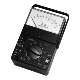
1. Block Diagram
2. Parts Identification and Functio
1. B mark
2. Spear
pointer
3. Zero
adjuster
screw
4. Input
resistance
switch
5. Power
on-off/battery
check switch
1.
B mark:
2.
Spear pointer
3.
Zero adjuster screw:
4.
lnput resistance switch:
5.
Power on-off/
battery check switch
6.
Scale plate:
7.
Carrying handle
8.
Meter cover fixing screw
9.
Meter cover
10.
Measuring range
selector switch:
11.
Input terminals:
12.
Case
Input
Range
resistance
Operating
selector
amplifier
selector
circuit
circuit
Overload
protective
Battery
circuit
check
circuit
6. Scale plate
7. Carrying
handle
B
ACV
8. Meter cover
fixing screw
9. Meter cover
10. Measuring
AC+DCmA
ACmA
10
10
range selector
1kΩ
1
1
1.5kΩ
switch
2kΩ
0.1
0.1
INPUT
11. Input
RESISTANCE
INPUT
terminals
10
300
BATT
ON
1
150
12. Case
0.1
OFF
DCmA
ACV
Fig. 1 Parts Identificatio
The battery is usable if the meter pointer is within
this range when the BATT/ON/OFF switch is
set to the BATT position.
To be turned with a screwdriver for readjusting
zero indication of the pointer.
Selects one of the three input resistances
according to the applicable standard.
The scale is double graduated in mA and AC V.
To be set to an appropriate position according to
the measuring item and range.
Accessory H-lead is to be connected to the "INPUT"
terminal, and L-lead to the "
Moving-coil
type DC
milliammeter
200 µA F.S.
Internal
resistance: 121 Ω
" (ground) terminal.
Advertisement
Table of Contents

Related Manuals for YOKOGAWA 3226


Summary of Contents for YOKOGAWA 3226
- Page 1 NOTE (7) Compact and lightweight for easy portable use. Model 3226 has AC + DCmA range. This is used mainly for the instrument which is Safety Precautions operated by DC after rectifying, AC to DC. Therefore, measured value on this range does not indicate RMS value, but the sum of DC and AC components directly.
- Page 2 2. After placing Model 3226 at the position of use, check that the meter pointer RV2 inside the case. coincides with the zero point of the scale, if not, adjust it accurately by Set the measuring range selector switch to the DC 1 mA position, turning the zero adjuster screw.
Need help?
Do you have a question about the 3226 and is the answer not in the manual?
Questions and answers