
Related Manuals for Strobel 325-40D-TP


Summary of Contents for Strobel 325-40D-TP
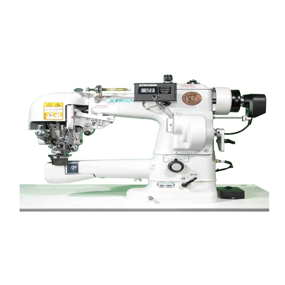
- Page 1 For the professional user Mechanic‘s Instructions Für den professionellen Anwender Mechanikeranleitung Class: 325-40D-TP Klasse: Model: Ausführung: Dated: Stand: S p e z i a l m a s c h i n e n G m b H...
- Page 2 The sign of quality ou find the Strobel trademark on every Strobel machine leaving our works. And with good reason. This symbol is a guarantee of the high quality of our products. Quality which creates trust – trust in our technology, our service and, not least of all, in our good name.
- Page 3 Justify your trust. If you wish to profit from the performance and efficiency of your Strobel machine as long as possible, exact handling and thorough care is necessary. For this reason we kindly request that you read the operating instructions closely.
-
Page 5: Table Of Contents
Mechanic’s Instructions STROBEL Class 325-40D-TP Contents General notes on safety .................... 3 General ........................5 Operating instructions ..................5 Class description, machine number and reference position ......5 Machine applications ..................5 Technical data ....................6 Brief setting instruction ................... 7 Instructions for the mechanic .................. - Page 6 Mains connection plan cl. general (AB611A with/without sewing machine lamp gen.) Connecting the sewing machine: 258.21.66 Electrical connection plan cl. 200, 300 259.00.51 Pneumatic circuit diagram cl. 218D-TP, 325-40D-TP 259.10.51 Pneumatic construction circuit diagram cl. 218D-TP, 325-40D-TP Connecting Plunger lowering: 258.10.16 Elecrtic diagram cl.
-
Page 7: General Notes On Safety
General notes on safety Every person in charge of setting up, operating, servicing and repairing the machine must first read and understand the operating instructions and particularly the safety instructions before starting up the machine. Failure to comply with the following safety instructions can lead to bodily injury or damage to the machine. - Page 8 14. Warning instructions given in the operating instructions that pertain to especially dangerous parts of the machine must be indicated at these positions using a safety symbol. Warning instructions given in the operating instructions that pertain to special injury hazards for operating personnel or technicians must be indicated at these positions using a safety symbol.
-
Page 9: General
General Operating instructions Any person involved in the installation, operation, maintenance and repair of the machine must have read and understood the operating instructions and mainly the safety instructions before starting the machine. Class description, machine number and reference position All references to directions, such as right, left, front, back etc. -
Page 10: Technical Data
Technical data Recommanded rated speed 1300 min Motor power 550 W Toothed belt pulley/machine Z = 38 Toothed belt profile HTD 5M-9 Stitch length-upper feed 2 – 8 mm (depend on shoulder pad) Kind of stitch: two thread blindstitch double lockstitch Stitch type Needle system GROZ-BECKERT 1717 VRUE... -
Page 11: Brief Setting Instruction
Brief setting instruction Plunger highest position to the needle 2 mm before centre plunger Plunger stops to the needle 2 mm after centre plunger Transport length lower feed 2 - 10 mm Transport length upper feed 4 - 12 mm Feed plate lift max.5 mm Feed plate rises... -
Page 12: Instructions For The Mechanic
Instructions for the mechanic A t t e n t i o n ! Upon working within the needle area, e.g. replacing the bobbin, never actuate the motor switch by stepping on the pedal! It is recommended to switch off the motor! Mounting the needle plate A t t e n t i o n ! Switch off machine electrically! -
Page 13: Remounting The Needle Plate
Fig. 1 3.1.2 Remounting the needle plate Re-mount the needle plate in reversed order. Removing and inserting hook After removing height stop limit lever for the hook, thread spreader (if existing), stitch plate, bevel wheel protective cover (rear of head) and bevel wheel 240.0020, the hook can be withdrawn to the front side. -
Page 14: Removing And Fitting The Bobbin Case (Fig. 4)
Upon mounting the teeth (pointed red) of bevel wheels (2) and (1) and the surface of the hook shaft must form a single line (Fig. 3). Fig. 3 3.2.1 Removing and fitting the bobbin case (Fig. 4) If a thread has become jammed between the bobbin case and shuttle, the bobbin case must be removed, otherwise the machine will be slowed down. -
Page 15: Adjusting Needle And Replacing Needle Glide Plate
Adjusting needle and replacing needle glide plate The needle glide plate is fixed on the lower side of the stitch plate. It can be withdrawn by loosening the screw 170.0263. The bottom of the needle channel of a sample needle glide plate screwed on to the stitch plate must be placed 0.01 - 0.04 mm higher than the theoretical needle radius. -
Page 16: Setting The Needle Lever Path (Fig. 1)
Setting the needle lever path (Fig. 1) After removing head cover and thread tension adjusting knob, turn needle lever sufficiently downwards, so that the eccentric bolt (1) can be reached with a screw driver through the, hole in the head provided for that purpose. After loosening the nut (6) and turning the bolt (in its rear area), the needle lever race is corrected. -
Page 17: Adjusting Feed Plate (Fig. 6 B)
Adjusting feed plate (Fig. 6 b) When preparing heavy goods, the feed plate must lift 5 mm from the stitch plate, i.e. basic setting. For fine to medium material a stroke of 2.5 mm is recommended, which is obtained by loosening the screw (1) and by moving the crank. -
Page 18: Plunger
Plunger The plunger forces the sewn material from underneathinto the needle plate opening, so that the needle can penetrate the sewing material. 3.9.1 Removing the plunger (Fig. 7) C a u t i o n ! Switch off the machine electrically! Remove needle plate, see point "Removing the needle plate". -
Page 19: Installation And Setting Of The Plunger (Fig. 7)
3.9.2 Installation and setting of the plunger (Fig. 7) Insert plunger into plunger sleeve. Ensure that pin (1) goes into the groove. Turn stitch depth knob 244.0322 all the way to the right (highest setting) Screw in threaded section (2) with plunger set screw (3) until it is flush with the plunger sleeve. -
Page 20: Setting The Digital Stitch Depth Display (Fig. 9)
3.9.4 Setting the digital stitch depth display (Fig. 9) When regulation knob (1) is turned all the way to the right, gearwheel (6) must be screwed onto the shaft of the multiturn potentiometer so that the digital display shows a value between 005 and 007 and the distance to gearwheel (4) is approximately 1.35 ±... -
Page 21: Setting The Plunger Lowering
3.10 Setting the plunger lowering For larger sewing material thickening, sometimes the stitch depth of a stitch should be reduced over a shorter or longer section. By adjusting the scale on the right of the stand, the plunger can be lowered from 0 to up to 3.8 mm by pushing a button. - Page 22 Fig. 11 Lever (1) on which the cylinder hangs must be set so that there is a free space of at least 0.5 to 1 mm between piston rod and eccentric (2). Secure lever (1) in this position on the eccentric with both threaded screws. (Fig. 12) Fig.
-
Page 23: Pneumatic Venting
3.11 Pneumatic venting A t t e n t i o n ! Danger of finger bruises in the area of pneumatically operated parts. 3.11.1 General On releasing the pedal to activate the motor, the machine moves into position and vents pneumatically. In this position, plunger, feed and presser plate must all be at the same level. - Page 24 258.00.35 Netz-Anschlussplan Kl. allg. (AB611A mit/ohne Nähleuchte allg.) Mains connection plan cl. gen. (AB611A with/without sewing light gen.) Kabelbefestigung mit Kabelbinder cable mounting with cable strap Nähleuchte (allg.) 3x 293.0290 sewing light (gen.) Kabelzugentlastung cable strain relief 193.0992 Netzanschluss Rechtes Gehäuseteil power connection right casing gn-ge / gn-ye...
- Page 25 LÜ ( MV1 ) 6,5A +24V(1) +24V(1) Control box Efka drive (1) Nominal voltage 24V, idle voltage max. 30V Designation Designation Colour code 37 pin Strobel operating manual Efka operating manual connection cable Sub-D Lifting (LÜ) Press foot lifting (FL) White brown...
- Page 26 259.00.51 Pneumatischer Schaltplan Kl. 218D-TP Ausf. 3 und Kl. 325-40D-TP ab Ausf. 9 Pneumatic circuit diagram cl. 218D-TP version 3 and cl. 325-40D-TP as of version 9 1V10 Am Deckel (Buchse und Schläuche kennzeichnen) 0 Z 1 6bar 10bar max 195.0521...
- Page 27 259.10.51 Pneumatischer Bauschaltplan Kl. 218D-TP Ausf. 3 und Kl. 325-40D-TP ab Ausf. 9 Pneumatic construction circuit diagram cl. 218D-TP version 3 and cl. 325-40D-TP as of version 9...
- Page 28 258.10.16 Elekrischer Schaltplan - Taucherabsenkung Kl. 218D-TP Ausf. 3 und Kl. 325-40D-TP ab Ausf. 9 Electrical wiring diagram - Plunger lowering Cl. 218D-TP version 3 and cl. 325-40D-TP as of version 9 ws wh gn gn br bn +24V br bn...
- Page 29 258.21.24 Elektrischer Anschlussplan Kl. 170, 560, ZM Digitalanzeige Electric connection diagram cl. 170, 560, ZM Digital display Steck-Adapter EA 9044 ws / wh socket adapter EA 9044 gn / gn br / bn 137kΩ 9 10 Widerstand resistor 5kΩ lin. Drehpotentiometer rotary potentiometer Kippschalter...
- Page 31 Und wir können noch mehr für Sie tun! Unser Lieferprogramm bietet für jede Branche und jegliche Anforderung genau die richtige Problemlösung. And we can do a lot more for you! Our range offers the correct problem solution for every branch and for all requirements. Für die Bekleidungs- Für die Schuh- Für die Polster-...
- Page 32 Then phone, write or simply come and see us. You can have further information about our products at any time, or experience the Strobel machines live in our show room. We’re looking forward to meeting you! Spe zi a l ma s c hine n G m bH...
Need help?
Do you have a question about the 325-40D-TP and is the answer not in the manual?
Questions and answers