
Related Manuals for Strobel 218D-TP-R


Summary of Contents for Strobel 218D-TP-R
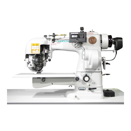
- Page 1 For the professional user Mechanic‘s Instructions Für den professionellen Anwender Mechanikeranleitung Class: 218D-TP-R Klasse: Model: Ausführung: Dated: Stand: S p e z i a l m a s c h i n e n G m b H...
- Page 2 The sign of quality ou find the Strobel trademark on every Strobel machine leaving our works. And with good reason. This symbol is a guarantee of the high quality of our products. Quality which creates trust – trust in our technology, our service and, not least of all, in our good name.
- Page 3 Justify your trust. If you wish to profit from the performance and efficiency of your Strobel machine as long as possible, exact handling and thorough care is necessary. For this reason we kindly request that you read the operating instructions closely.
-
Page 5: Table Of Contents
Mechanic's instructions STROBEL Class 218D-TP-R Contents General notes on safety .................... 5 General ........................7 Operating instructions ..................7 Class description, machine number and reference position left/right ..... 7 Machine applications ..................7 Technical data ....................8 Brief setting instruction ................... 9 Hints for repair and settings .................. - Page 6 Plunger ......................20 3.7.1 Removing the plunger (Fig. 10) ............20 3.7.2 Fitting the plunger (Fig. 10) .............. 21 3.7.3 Adjusting plunger motion (Fig. 11) ........... 21 3.7.4 Adjusting the digital stitch depth (Fig. 12) ........22 Setting the plunger lowering (Fig. 13, Fig. 14, Fig. 15) ......... 23 Thread spreader ...................
- Page 7 Cl. 218D-TP as of version 3 and Cl. 325-40D-TP as of version 9 259.00.62 Pneumatic circuit diagram cl. 218D-TP-R 259.10.62 Pneumatic construction circuit diagram cl. 218D-TP-R Connecting Plunger lowering and spot tack: 258.10.25 Electric circuit diagram cl. 218D-TP-R Connecting digital display: 258.21.24...
- Page 8 MA_218D-TP-R_A4_181015_en...
-
Page 9: General Notes On Safety
General notes on safety Every person in charge of setting up, operating, servicing and repairing the machine must first read and understand the operating instructions and particularly the safety instructions before starting up the machine. Failure to comply with the following safety instructions can lead to bodily injury or damage to the machine. - Page 10 14. Warning instructions given in the operating instructions that pertain to especially dangerous parts of the machine must be indicated at these positions using a safety symbol. Warning instructions given in the operating instructions that pertain to special injury hazards for operating personnel or technicians must be indicated at these positions using a safety symbol.
-
Page 11: General
General Operating instructions Any person involved in the installation, operation, maintenance and repair of the machine must have read and understood the operating instructions and mainly the safety instructions before starting the machine. Class description, machine number and reference position left/right For side-referenced descriptions (right, left), the operating side of the machine is the starting base. -
Page 12: Technical Data
Technical data Recommanded rated speed 1300 min Motor power 550 W Toothed belt pulley/machine z = 38 Toothed belt profile HTD 5M-9 Stitch length 2 - 6 mm (depend on fabric) Kind of stitch: two thread blindstitch lockstitch Stitch type Needle system GROZ-BECKERT 1717 VRUE Needle size... -
Page 13: Brief Setting Instruction
Brief setting instruction Theoretic needle radius 43.6 mm Theoretic needle glide plate 43.59 -0.03 mm Stroke of loop 2.8 mm Distance from looper point to needles eye 1.8 ±0.2 mm Highest position of plunger 2 mm before plunger center in relation to needle Plunger stops in relation to needle 2 mm after plunger center Start of feed motion in case... -
Page 14: Hints For Repair And Settings
Hints for repair and settings A t t e n t i o n , danger! Observe safety and operating instructions before realizing any maintenance and repair works. Failure to do so may result in heavy bodily injuries. Mounting the needle plate A t t e n t i o n ! Switch off machine electrically! Needle plates are set at works and can be replaced easily as complete kit. -
Page 15: Remounting The Needle Plate
Fig. 1 3.1.2 Remounting the needle plate Remount the needle plate in reversed order. 3.1.3 Setting the needle plate (Fig. 1) The theoretical needle radius of 43.6 mm should be 0.01 - 0.04 mm smaller at the needle slide plate; in other words, a checked needle is raised by 0.01 - 0.04 mm. -
Page 16: Adjusting The Needle
3.1.4 Adjusting the needle A t t e n t i o n ! Switch off machine electrically! The needle is adjusted in a lateral direction so that it is situated centrally in relation to the needle plate (i.e. between the two screw holes). 3.1.5 Replacing the needle slide plate (Fig. -
Page 17: Needle Lever
Needle lever A t t e n t i o n ! Switch off machine electrically! 3.2.1 Setting the needle lever path (Fig. 1) After removing the head cover and the thread tension adjustment button, the needle lever must be turned down so far, that the eccentric bolt (1) can be reached with a screw driver through the hole provided in the head. -
Page 18: Stroke Of Loop
Stroke of loop Stroke of loop means the needle race from its lowest position to the spot where the lower point is placed on top of the center of the needle. 3.3.1 Setting the needle stroke (Fig. 3) A t t e n t i o n ! Switch off machine electrically! Normally is a loop stroke of 2.8 mm. -
Page 19: Looper
Looper 3.4.1 Removing and re-mounting the looper (Fig. 3 + Fig. 4) A t t e n t i o n ! Switch off machine electrically! Dismantle the following parts: Cover (rear of head), needle, needle plate, angle lever (2) (Fig. 4) with bolt (5) and spring (1) (Fig. -
Page 20: Setting The Shuttle In Relation To The Needle (Fig. 5)
3.4.2 Setting the shuttle in relation to the needle (Fig. 5) The gap between the shuttle tip and a 90 needle must max. 0.2 mm. If it is necessary to adjust the shuttle, then this is done by slackening the cylinder head screw (1) and turning the eccentric bushing (2). -
Page 21: Thread Tension - Bobbin Thread (Fig. 7)
3.4.4 Thread tension - bobbin thread (Fig. 7) The leaf spring (2) regulates the bobbin thread tension. By turning the flat-head screw with catch (1), the leaf spring must be adjusted in such a way that when the bobbin is inserted, and the thread is correctly pulled under the leaf spring and the bobbin case is released, the latter, together with the bobbin, drops slowly down. -
Page 22: Feed Motion
3.5.1 Feed (bottom feed) (Fig. 9) The machine cl. 218D-TP-R is factory-fitted with a pyramid-teethed feed (3). 3.5.2 Setting the feed motion (Fig. 8) The feed cam (1) on the main shaft must be set so that feed begins when the eye of the needle is located 5 ±1 mm before centre of the plunger on its return... -
Page 23: Presser Plate
Presser plate When the initial stitch is made, the presser plate presses the sewn item from below against the needle plate. During feed, the presser plate should life 4 - 5 mm from the needle plate when working with thick sewing material, and 2.5 mm when working with thin to medium sewing material. -
Page 24: Plunger
Plunger The plunger forces the sewn material from underneath into the needle plate opening, so that the needle can penetrate the sewing material. 3.7.1 Removing the plunger (Fig. 10) A t t e n t i o n ! Switch off machine electrically! Unscrew threaded screw (2) with plunger check screw (3), until it is flushed with the plunger sleeve. -
Page 25: Fitting The Plunger (Fig. 10)
3.7.2 Fitting the plunger (Fig. 10) Fitting takes place in reverse order. However, the following points must be observed for precise adjustment: the cylindrical pin (1) must engage in the groove of the plunger sleeve. Turn stitch-depth adjustment knob (1) (Fig. 12) clockwise, as far as the stop (highest position). -
Page 26: Adjusting The Digital Stitch Depth (Fig. 12)
Fig. 11 3.7.4 Adjusting the digital stitch depth (Fig. 12) If the adjustment knob (1) is turned clockwise as far as the stop, the toothed wheel (6) must be screwed tightly onto the shaft of the helical potentiometer so that a value of between 003 and 006 is displayed on the digital display, and the distance to the toothed wheel (4) is approx. -
Page 27: Setting The Plunger Lowering (Fig. 13, Fig. 14, Fig. 15)
Setting the plunger lowering (Fig. 13, Fig. 14, Fig. 15) For larger sewing material thickening, sometimes the stitch depth of a stitch should be reduced over a shorter or longer section. By adjusting the scale on the right of the stand, the plunger can be lowered from 0 to up to 3.8 mm by pushing a button. - Page 28 Set the plunger to the highest possible point and adjust the eccentric (1) (Fig. 14) to approx. 15° at the stop of scale (2) (Fig. 14) at pin (3) (Fig. 14). Fix the scale in this position on the eccentric. Fig.
- Page 29 Lever (1) (Fig. 15) on which the cylinder hangs must be set so that there is a free space of at least 0.5 to 1 mm between piston rod and eccentric (2) (Fig. 15). Secure lever (1) (Fig. 15) in this position on the eccentric with both threaded screws.
-
Page 30: Thread Spreader
Thread spreader It is possible to produce a cross-stitch using the thread spreader. The two fingers of the thread spreader take hold of the thread between the sewing material and the eye of the needle and place it under slight tension, at an angle to the movement of the needle, in a groove in the needle plate. -
Page 31: Seam Lock
3.10 Seam lock A t t e n t i o n ! Switch off machine electrically! A t t e n t i o n ! Danger of finger bruises in the area of pneumatically operated parts. 3.10.1 General (Fig. 17) Refer to the sewing drive instructions for the parameter settings of the start and end backtacks. -
Page 32: Pneumatic Venting
3.11 Pneumatic venting A t t e n t i o n ! Danger of finger bruises in the area of pneumatically operated parts. 3.11.1 General To vent the machine, pneumatic venting can be supplied in place of the knee lever. - Page 33 258.00.35 Netz-Anschlussplan Kl. allg. (AB611A mit/ohne Nähleuchte allg.) Mains connection plan cl. gen. (AB611A with/without sewing light gen.) Kabelbefestigung mit Kabelbinder cable mounting with cable strap Nähleuchte (allg.) 3x 293.0290 sewing light (gen.) Kabelzugentlastung cable strain relief 193.0992 Netzanschluss Rechtes Gehäuseteil power connection right casing gn-ge / gn-ye...
- Page 34 LÜ ( MV1 ) 6,5A +24V(1) +24V(1) Control box Efka drive (1) Nominal voltage 24V, idle voltage max. 30V Designation Designation Colour code 37 pin Strobel operating manual Efka operating manual connection cable Sub-D Lifting (LÜ) Press foot lifting (FL) White brown...
- Page 35 258.10.16 Elekrischer Schaltplan - Taucherabsenkung Kl. 218D-TP Ausf. 3 und Kl. 325-40D-TP ab Ausf. 9 Electrical wiring diagram - Plunger lowering Cl. 218D-TP version 3 and cl. 325-40D-TP as of version 9 ws wh gn gn br bn +24V br bn br bn +24V ws wh...
- Page 36 259.00.62 Pneumatischer Schaltplan Kl. 218D-TP-R ab Ausf. 4 Pneumatic circuit diagram cl. 218D-TP-R as of version 4 195.0549 0 Z 1 Wartungseinheit service unit 1 V 1 4/2-Magnetventil "Lüftung" 4/2-solenoid-way valve "lifting" 1 V 2 4/2-Magnetventil "Taucherabsenkung" 4/2-solenoid-way valve "plunger lowering"...
- Page 37 259.10.62 Pneumatischer Bauschaltplan Kl. 218D-TP-R ab Ausf. 4 Pneumatic construction circuit diagram cl. 218D-TP-R as of version 4...
- Page 38 258.10.25 Elekrischer Schaltplan - Taucherabsenkung und Punktriegel Kl. 218D-TP-R ab Ausf. 4 Electrical wiring diagram - Plunger lowering ans spot tack Cl. 218D-TP as of version 4 Sperrdiode S2 (R) +24V +24V S1 (TP) +24V 1V3 (R) 1V2 (TP) vom Nähantrieb 1V1 (LÜ)
- Page 39 258.21.24 Elektrischer Anschlussplan Kl. 170, 560, ZM Digitalanzeige Electric connection diagram cl. 170, 560, ZM Digital display Steck-Adapter EA 9044 ws / wh socket adapter EA 9044 gn / gn br / bn 137kΩ 9 10 Widerstand resistor 5kΩ lin. Drehpotentiometer rotary potentiometer Kippschalter...
- Page 41 Und wir können noch mehr für Sie tun! Unser Lieferprogramm bietet für jede Branche und jegliche Anforderung genau die richtige Problemlösung. And we can do a lot more for you! Our range offers the correct problem solution for every branch and for all requirements. Für die Bekleidungs- Für die Schuh- Für die Polster-...
- Page 42 Then phone, write or simply come and see us. You can have further information about our products at any time, or experience the Strobel machines live in our show room. We’re looking forward to meeting you! Spe zi a l ma s c hine n G m bH...
Need help?
Do you have a question about the 218D-TP-R and is the answer not in the manual?
Questions and answers