
Related Manuals for Strobel 4


Summary of Contents for Strobel 4
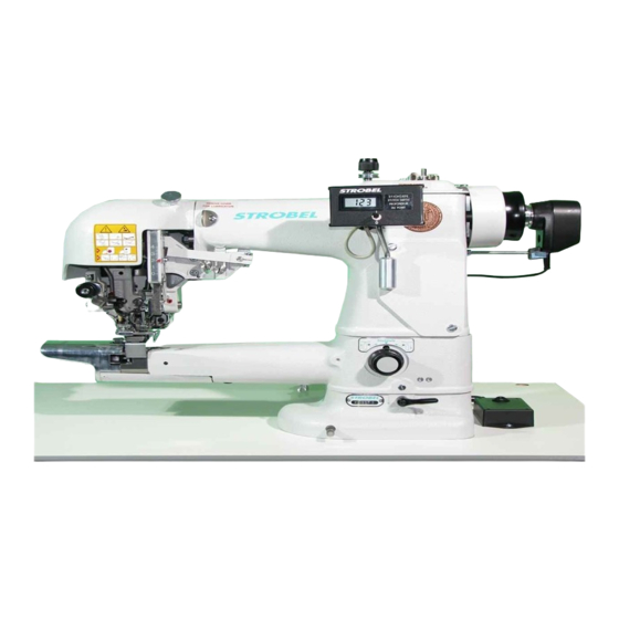
- Page 1 For the professional user Mechanic‘s Instructions Für den professionellen Anwender Mechanikeranleitung Class: 560-11, -21 Klasse: Model: Ausführung: Dated: Stand: S p e z i a l m a s c h i n e n G m b H...
- Page 2 The sign of quality ou find the Strobel trademark on every Strobel machine leaving our works. And with good reason. This symbol is a guarantee of the high quality of our products. Quality which creates trust – trust in our technology, our service and, not least of all, in our good name.
- Page 3 Justify your trust. If you wish to profit from the performance and efficiency of your Strobel machine as long as possible, exact handling and thorough care is necessary. For this reason we kindly request that you read the operating instructions closely.
-
Page 5: Table Of Contents
Setting the thread holder (Fig. 1) ............. 11 Setting the needle lever ................12 3.2.1 Lateral setting of needle lever (Fig. 3 and Fig. 4) ......12 3.2.2 Setting of the needle lever in relation to the thread take-up (Fig. 5) 13 3.2.3... - Page 6 (Fig. 11, Fig. 13, Fig. 14 and Fig. 15) ..........21 3.6.3 Mounting and setting of the plunger drive (Fig. 12, Fig. 16, Fig. 17 and Fig. 18) ..........24 3.6.4 Setting the digital stitch depth display (Fig. 14 and Fig. 19) ..... 27 Plunger plate ....................28 3.7.1 Setting the plunger plate (Fig.
- Page 7 Electrical connection diagram cl. 560-21 from version 4 259.00.57 Pneumatic circuit diagram cl. 560 from version 4 259.10.57 Pnaumatic construction circuit diagram cl. 560 from version 4 Connecting digital display: 258.21.24 Electric connection diagram Kl. 170, 560, ZM Subject to change without prior notice...
- Page 8 MA_560_A4_180619_en...
-
Page 9: General Notes On Safety
General notes on safety Every person in charge of setting up, operating, servicing and repairing the machine must first read and understand the operating instructions and particularly the safety instructions before starting up the machine. Failure to comply with the following safety instructions can lead to bodily injury or damage to the machine. - Page 10 14. Warning instructions given in the operating instructions that pertain to especially dangerous parts of the machine must be indicated at these positions using a safety symbol. Warning instructions given in the operating instructions that pertain to special injury hazards for operating personnel or technicians must be indicated at these positions using a safety symbol.
-
Page 11: General
General Operating instructions Any person involved in the installation, operation, maintenance and repair of the machine must have read and understood the operating instructions and mainly the safety instructions before starting the machine. Class identification, serial number and orientation of the machine The operating side of the machine is the basis for descriptions referring to sides. -
Page 12: Technical Data
Technical Data Recommended rated speed 1600 min Motor power 400 W Number of tack stitches 6, 8, 10, 12, 14 Toothed belt pulley/machine Z = 38 Toothed belt profile HDT 5M-9 Kind of stitch Single thread blindstitch spot tacking Stitch type Needle system GROZ-BECKERT 1717 VRUE Needle size... -
Page 13: Instructions For Repair And Settings
Instructions for repair and settings A T T E N T I O N , d a n g e r ! Observe safety and operating instructions before realizing any maintenance and repair works. Failure to do so may result in heavy bodily injuries. Mounting the needle plate A T T E N T I O N ! Switch off machine electrically! -
Page 14: Setting The Needle Plate (Fig. 1 And Fig. 2)
Fig. 1 3.1.3 Setting the needle plate (Fig. 1 and Fig. 2) The theoretic needle radius of 43.6 mm should be by 0.01 - 0.04 mm smaller at the needle glide plate; i.e. a checked needle is lifted by 0.01 - 0.04 mm. Control by means of a dial gauge. If this setting is correct, there should be a distance of 0.03 - 0.06 mm between needle and needle plate radius. -
Page 15: Setting The Needle (Fig. 1)
In lateral direction a needle No. 90 is set in a way that at the left hand needle penetration there is a distance of 0.15 - 0.2 mm between the left hand needle side and the needle plate groove. For resetting, loosen screw (4) and displace part (5). -
Page 16: Setting The Needle Lever
Switch off machine electrically! 3.2.1 Lateral setting of needle lever (Fig. 3 and Fig. 4) Control cam (1) is set in a way that the needle lever being in its lowest position (lower dead point) the radius corresponding to the needle penetration (right hand needle penetration small radius, left hand needle penetration large radius), stands exactly under roll (2). -
Page 17: Setting Of The Needle Lever In Relation To The Thread Take-Up (Fig. 5)
3.2.2 Setting of the needle lever in relation to the thread take-up (Fig. 5) By turning eccentric disc (1) on shaft (2) the movement of the needle lever is set in a way that needle lever and thread take up move downwards simultaneously. -
Page 18: Setting The Stitch Width (Fig. 6)
If materials or threads are sure where - due to their structure – the loop is too small or too large, reset the loop stroke as follows: Loosen both screws in gearwheel (4) Turn endless screw (5) at the back side of the head to the right or to the... -
Page 19: Looper
Looper 3.4.1 Removing and remounting the looper (Fig. 7) A T T E N T I O N ! Switch off machine electrically! Remove the needle plate, loosen threaded pin (1) in the looper shaft and remove the looper downwards. -
Page 20: Thread Take-Up
By adjusting the eccentric (1) by loosening the screws (2) ((3) in the connecting rod) of the date of the take-up lever movement can be adjusted. By moving the cross bearing (4) on the take-up lever (5) whose rash can be changed (factory setting 48 mm). -
Page 21: Upper Thread Tension (Fig. 9)
3.5.2 Upper thread tension (Fig. 9) The upper thread tension mainly regulates the seam appearance. Depending on the material these value have to be modified to obtain an optimum seam appearance. 3.5.3 Lower thread tension (Fig. 9) The lower thread tension regulates the length of the initial thread. →... -
Page 22: Setting The Thread Wiper (Fig. 10)
3.5.4 Setting the thread wiper (Fig. 10) A T T E N T I O N ! Switch off machine electrically! In the lower Stop position the distance between needle plate and thread wiper should be 0.5 mm. The upper end is by loosening the nut (1) and turn the eccentric bolt (2) set. -
Page 23: Plunger
Plunger The plunger presses the material upwards into the needle plate opening to enable the needle to penetrate the material. At plunger zero-point (plunger value “0” / plunger is at its top-most position) the needle is lifted 0.1 – 0.2 mm from the plunger. For the setting refer to: Cl. - Page 24 Fig. 11 560-11 Fig. 12 560-21 MA_560_A4_180619_en...
-
Page 25: Mounting And Setting The Plunger Drive (Fig. 11, Fig. 13, Fig. 14 And Fig. 15)
(3) and secure with nut (4). (Fig. 13) Mount shaft (5) and secure to the surface with the 2 threaded pins (6). Then tighten the last threaded pin (7) and secure the rest of the nuts (4). (Fig. 13) Setting lever (4) on shaft (5) (Fig. 14): Lightly clamp the lever on the shaft. - Page 26 Loosen screw (1) slightly in lever (2) and beat the lever upwards until the plunger lifts the needle by 0.1 - 0.2 mm; tighten well screw (1). (Fig. 15) A T T E N T I O N ! Make sure that lever (2) is in axial position. (Fig. 15) Finally fix set collar (3) to lever (2).
- Page 27 Fig. 15 MA_560_A4_180619_en...
-
Page 28: Mounting And Setting Of The Plunger Drive (Fig. 12, Fig. 16, Fig. 17 And Fig. 18)
(3) and secure with nut (4). (Fig. 16) Mount shaft (5) and secure to the surface with the 2 threaded pins (6). Then tighten the last threaded pin (7) and secure the rest of the nuts (4). (Fig. 16) Setting of the lever (8) on shaft (5) (Fig. 16):... - Page 29 Switch the machine off again by the main switch and pull the power plug. Push the plunger up by hand (until stop by cam). 10. Loosen screw (1) slightly in lever (2) beat the lever upwards until the plunger lifts the needle by 0.1 - 0.2 mm; tighten well screw (1). (Fig. 18) A T T E N T I O N ! Make sure that lever (2) is in axial position.
- Page 30 Fig. 18 MA_560_A4_180619_en...
-
Page 31: Setting The Digital Stitch Depth Display (Fig. 14 And Fig. 19)
3.6.4 Setting the digital stitch depth display (Fig. 14 and Fig. 19) Class 560-11 only A T T E N T I O N ! Switch off machine electrically! The digital stitch depth display is available as optional extra and can also be mounted to machines already in use. -
Page 32: Plunger Plate
2 mm. Regulation by means of lever (3) on the magnet shaft. Set collar (4) prefig.nts part (5) from moving upwards. Mount set collar (4) in a way that (5) and knife (2) can do the cutting movement without jamming (play 0.2 mm). - Page 33 258.21.72en Electrical connection diagram Cl. 560-11 as of version 4 Head - Sewing machine STM2 thread trimmer (FA) 195.0038 (1) Nominal voltage 24V =, no-load voltage max. 30V = Machine cover Plug Desccription Color code Strobel-instruction Sub-D connecting line manual...
- Page 34 258.21.73en Electrical connection diagram Cl. 560-21 from version 4 Head - Sewing machine STM5 step motor (SM) A" B" STM2 thread trimmer (FA) STM1 hall sensor 195.0038 (1) Nominal voltage 24V =, no-load voltage max. 30V = Machine cover Plug...
- Page 35 259.00.57 Pneumatischer Schaltplan Kl. 560 ab Ausf. 4 Pneumatic circuit diagram cl. 560 as of version 4 1 A 3 1 A 2 1 M 1 1 A 1 Am Maschinendeckel (Buchse und Schläuche kennzeichnen) on the machine cover (mark bush and tubes)
- Page 36 259.10.57en Pneumatic construction circuit diagram cl. 560 from version 4...
- Page 37 258.21.24 Elektrischer Anschlussplan Kl. 170, 560, ZM Digitalanzeige Electric connection diagram cl. 170, 560, ZM Digital display Steck-Adapter EA 9044 ws / wh socket adapter EA 9044 gn / gn br / bn 137kΩ 9 10 Widerstand resistor 5kΩ lin. Drehpotentiometer rotary potentiometer Kippschalter...
- Page 39 Und wir können noch mehr für Sie tun! Unser Lieferprogramm bietet für jede Branche und jegliche Anforderung genau die richtige Problemlösung. And we can do a lot more for you! Our range offers the correct problem solution for every branch and for all requirements. Für die Bekleidungs- Für die Schuh- Für die Polster-...
- Page 40 Then phone, write or simply come and see us. You can have further information about our products at any time, or experience the Strobel machines live in our show room. We’re looking forward to meeting you! Spe zi a l ma s c hine n G m bH...
Need help?
Do you have a question about the 4 and is the answer not in the manual?
Questions and answers