Table of Contents
Advertisement
Quick Links
Pos : 2 /D okumentati on allgemein/Ei nband/Ei nband H andbuch - Dec kbl att ohne Variantenfel d (Standar d) @ 9\mod_1285229289866_0.doc x @ 64941 @ @ 1
Manual
®
EPSITRON
Electronic Circuit Breaker
787-1668(/xxxx-xxxx)
24 VDC, 8 × 2 ... 10 A
Version 1.1.0
Pos : 3 /Alle Serien (Allgemeine M odul e)/Hinweise z ur Dokumentation/Impres sum für Standardhandbüc her - allg. Angaben, Ansc hriften, Tel efonnummer n und E-Mail-Adres sen @ 3\mod_1219151118203_21.doc x @ 21060 @ @ 1
Advertisement
Chapters
Table of Contents

Related Manuals for WAGO EPSITRON 787-1668 Series


Summary of Contents for WAGO EPSITRON 787-1668 Series
- Page 1 Pos : 2 /D okumentati on allgemein/Ei nband/Ei nband H andbuch - Dec kbl att ohne Variantenfel d (Standar d) @ 9\mod_1285229289866_0.doc x @ 64941 @ @ 1 Manual ® EPSITRON Electronic Circuit Breaker 787-1668(/xxxx-xxxx) 24 VDC, 8 × 2 … 10 A Version 1.1.0 Pos : 3 /Alle Serien (Allgemeine M odul e)/Hinweise z ur Dokumentation/Impres sum für Standardhandbüc her - allg.
- Page 2 EPSITRON® 787-1668 Electronic Circuit Breaker © 2014 by WAGO Kontakttechnik GmbH & Co. KG All rights reserved. WAGO Kontakttechnik GmbH & Co. KG Hansastraße 27 D-32423 Minden Phone: +49 (0) 571/8 87 – 0 Fax: +49 (0) 571/8 87 – 1 69 E-Mail: info@wago.com...
-
Page 3: Table Of Contents
EPSITRON® Table of Contents 787-1668 Electronic Circuit Breaker Pos : 5 /D okumentati on allgemein/Verzeic hnisse/Inhalts verz eichnis - Ü berschrift oG und Verzei chnis @ 3\mod_1219151230875_21.doc x @ 21063 @ @ 1 Table of Contents Table of Contents ....................3 Notes about this Documentation .............. - Page 4 Table of Contents EPSITRON® 787-1668 Electronic Circuit Breaker 6.2.3 Trip Curve for the 6 A Circuit Breaker with Active Current Limitation 787-1668/0006-1000 ................30 6.2.3.1 Response of the Electronic Circuit Breaker with Active Current Limitation ..................31 6.2.3.1.1 Response 1: Over-current present that is greater than Threshold 3 ....................
-
Page 5: Notes About This Documentation
Reproduction, translation, electronic and phototechnical filing/archiving (e.g., photocopying) as well as any amendments require the written consent of WAGO Kontakttechnik GmbH & Co. KG, Minden, Germany. Non-observance will involve the right to assert damage claims. Pos : 12.2 /Dokumentation allgemei n/Glieder ungs elemente/---Seitenwechs el--- @ 3\mod_1221108045078_0.doc x @ 21810 @ @ 1 Manual Version 1.1.0... -
Page 6: Symbols
Notes about this Documentation EPSITRON® 787-1668 Electronic Circuit Breaker Pos : 12.3 /All e Seri en ( Allgemei ne Module)/Ü bers chriften für alle Serien/Hinweis z ur D okumentati on/Symbole - Ü berschrift 2 @ 13\mod_1351068042408_21.doc x @ 105270 @ 2 @ 1 Symbols Pos : 12.4.1 /All e Serien ( Allgemei ne Module)/Wic htige Erläuterungen/Sicherheits- und sons tige Hinweis e/Gefahr/Gefahr: _War nung vor Personenschäden allgemei n_ - Erl äuter ung @ 13\mod_1343309450020_21.doc x @ 101029 @ @ 1 Personal Injury! - Page 7 EPSITRON® Notes about this Documentation 787-1668 Electronic Circuit Breaker Additional Information: Refers to additional information which is not an integral part of this documentation (e.g., the Internet). Pos : 12.5 /Dokumentation allgemei n/Glieder ungs elemente/---Seitenwechs el--- @ 3\mod_1221108045078_0.doc x @ 21810 @ @ 1 Manual Version 1.1.0...
-
Page 8: Number Notation
Table 3: Font conventions Font type Indicates italic Names of paths and data files are marked in italic-type. e.g.: C:\Programme\WAGO-I/O-CHECK Menu Menu items are marked in bold letters. e.g.: Save A greater-than sign between two names means the selection of a >... -
Page 9: Important Notes
2.1.1 Subject to Changes WAGO Kontakttechnik GmbH & Co. KG reserves the right to provide for any alterations or modifications that serve to increase the efficiency of technical progress. WAGO Kontakttechnik GmbH & Co. KG owns all rights arising from the granting of patents or from the legal protection of utility patents. -
Page 10: Technical Condition Of Specified Devices
The components to be supplied Ex Works, are equipped with hardware and software configurations, which meet the individual application requirements. WAGO Kontakttechnik GmbH & Co. KG will be exempted from any liability in case of changes in hardware or software as well as to non-compliant usage of components. -
Page 11: Safety Advice (Precautions)
Control systems connected to the device may also be damaged! Return the defective device directly to WAGO. Pos : 15.17 /Serie 787 ( EPSITR ON)/Wichtige Erläuterungen/Sic herheits- und sonstige Hinweis e/Achtung/Achtung: F ederleis ten nicht unter Last stec ken oder ziehen! @ 18\mod_1392900217463_21.doc x @ 145941 @ @ 1... - Page 12 Important Notes EPSITRON® 787-1668 Electronic Circuit Breaker Attach the free ends of the conductors using a strain relief device! Provide appropriate strain relief means to attach and cap any free ends of the conductors. Female connectors can be pulled out of the male connectors by high vibration levels or shock impacts.
-
Page 13: Device Description
EPSITRON® Device Description 787-1668 Electronic Circuit Breaker Pos : 17 /All e Seri en (Allgemei ne Module)/Ü berschriften für alle Serien/Gerätebesc hreibung/Gerätebeschr eibung - Übersc hrift 1 @ 3\mod_1233756084656_21.doc x @ 27096 @ 1 @ 1 Device Description Pos : 18.1 /Serie 787 (EPSITRON)/Ger ätebesc hrei bung/Bes chr eibung/Anwendung/Anwendung 787-1668 @ 12\mod_1342431638280_21.doc x @ 100295 @ @ 1 The 787-1668 electronic circuit breaker reliably protects up to 8 load circuits against short circuiting and overloading. -
Page 14: View
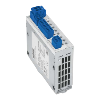
Device Description EPSITRON® 787-1668 Electronic Circuit Breaker Pos : 20 /All e Seri en (Allgemei ne Module)/Ü berschriften für alle Serien/Gerätebesc hreibung/Ansic ht - Ü berschrift 2 @ 4\mod_1240984217343_21.doc x @ 31958 @ 2 @ 1 View Pos : 21 /Serie 787 (EPSITRON)/Ger ätebesc hrei bung/Ansicht/Ansic ht 787- 1668 @ 13\mod_1343371041650_21.doc x @ 101060 @ @ 1 Figure 1: View of device Table 5: Key for "Device view"... -
Page 15: Connectors
EPSITRON® Device Description 787-1668 Electronic Circuit Breaker Pos : 23 /All e Seri en (Allgemei ne Module)/Ü berschriften für alle Serien/Gerätebesc hreibung/Ansc hlüsse - Übersc hrift 2 @ 4\mod_1240984262656_21.doc x @ 31961 @ 2 @ 1 Connectors Pos : 24.1 /Serie 787 (EPSITRON)/Wic htige Erläuterungen/Sicher heits- und s ons tige Hi nweis e/Ac htung/Ac htung: F ederl eisten nic ht unter Las t stec ken oder zi ehen! @ 18\mod_1392900217463_21.doc x @ 145941 @ @ 1 Do not plug in or disconnect the female connector while a load is applied! Only plug in or disconnect the female connectors when the device is not live! Failure to observe this can result in damage to the contacts due to arcing! -
Page 16: Fuse-Protected Outputs
Device Description EPSITRON® 787-1668 Electronic Circuit Breaker Total current exceeds 40 A! Distribute the current to input terminals "IN1" and "IN2" when the total current should exceed 40°A, as otherwise the plug-in connectors will become overheated and can be damaged or destroyed. Pos : 24.7 /Serie 787 (EPSITRON)/Ger ätebesc hrei bung/Ans chl üss e/Ans chl üss e 787-1668 - Abgesic herte Ausgänge @ 12\mod_1342099465661_21.doc x @ 100030 @ 3 @ 1 3.2.2 Fuse-Protected Outputs... -
Page 17: Display Elements
EPSITRON® Device Description 787-1668 Electronic Circuit Breaker Pos : 26 /All e Seri en (Allgemei ne Module)/Ü berschriften für alle Serien/Gerätebesc hreibung/Anz eigeel emente - Übersc hrift 2 @ 4\mod_1240984390875_21.doc x @ 31964 @ 2 @ 1 Display Elements Pos : 27 /Serie 787 (EPSITRON)/Ger ätebesc hrei bung/Anzeigeelemente/Anz eigeelemente 787-1668 @ 13\mod_1343380073501_21.doc x @ 101066 @ @ 1 A multi-colored LED, integrated in a button, is assigned to each output channel. -
Page 18: Operating Elements
Device Description EPSITRON® 787-1668 Electronic Circuit Breaker Pos : 29 /All e Seri en (Allgemei ne Module)/Ü berschriften für alle Serien/Gerätebesc hreibung/Bedienel emente - Ü berschrift 2 @ 4\mod_1239191655456_21.doc x @ 30439 @ 2 @ 1 Operating Elements Pos : 30 /Serie 787 (EPSITRON)/Ger ätebesc hrei bung/Bedi enelemente/Bedienel emente 787- 1668 @ 12\mod_1341816912585_21.doc x @ 99130 @ 33 @ 1 3.4.1 Buttons A button is assigned to each output channel. -
Page 19: Rotary Switch
EPSITRON® Device Description 787-1668 Electronic Circuit Breaker 3.4.2 Rotary Switch A rotary switch, which can be used to set the output currents for the individual outputs, is assigned to each output channel. The following settings are possible: Table 11: Rotary Switch Settings Variant Setting 787-1668... -
Page 20: Technical Data
Device Description EPSITRON® 787-1668 Electronic Circuit Breaker Pos : 32 /All e Seri en (Allgemei ne Module)/Ü berschriften für alle Serien/Gerätebesc hreibung/Technisc he Daten - Ü berschrift 2 @ 3\mod_1232967587687_21.doc x @ 26924 @ 2 @ 1 Technical Data Pos : 33 /Serie 787 (EPSITRON)/Ger ätebesc hrei bung/T ec hnis che D aten/Technisc he Daten 787-1668 @ 12\mod_1341822484504_21.doc x @ 99133 @ 33333 @ 1 3.5.1 Device Data Table 12: Device data... -
Page 21: Technical Data For "Input
24 V 787-1668, 1.32 W 787-1668/0106-0000: 1.15 W 787-1668/0006-1000: Input modules WAGO-MULTI CONNECTION SYSTEM (MCS), 721 Series Connection: 0.08 mm² … 2.5 mm² (maximum 1.5 mm² with insulated ferrule) WAGO-MULTI CONNECTION SYSTEM (MCS), 831 Series Connection: 0.5 mm² … 10 mm²... -
Page 22: Technical Data For "Output
Recovery stability maximum 35 V Parallel connection of output channels prohibited Series connection of output channels prohibited Output terminals WAGO-MULTI CONNECTION SYSTEM (MCS), 721 Series Connection: 0.08 mm² … 2.5 mm² (maximum 1.5 mm² with insulated ferrule) Manual Version 1.1.0... -
Page 23: Technical Data For "Ambient Conditions
Signal Output S3 24 VDC, active high, short-circuit proof maximum current carrying capacity: 25 mA Control and Signaling Terminals WAGO-MULTI CONNECTION (S1, S2, S3) SYSTEM (MCS), 721 Series Connection: 0.08 mm² … 2.5 mm² (maximum 1.5 mm² with insulated ferrule) Pos : 34 /D okumentation allgemei n/Glieder ungs elemente/---Seitenwechs el--- @ 3\mod_1221108045078_0.doc x @ 21810 @ @ 1... -
Page 24: Approvals
Device Description EPSITRON® 787-1668 Electronic Circuit Breaker Pos : 35 /All e Seri en (Allgemei ne Module)/Ü berschriften für alle Serien/Gerätebesc hreibung/Zul ass ungen - Übersc hrift 2 @ 3\mod_1224055364109_21.doc x @ 24030 @ 2 @ 1 Approvals Pos : 36.1 /Serie 787 (EPSITRON)/Ger ätebesc hrei bung/Z ulassungen/Z ulassungen Elektr. Sc hutzsc halter 787- xxxx Allgemein, Standar dvers. und spezif. Variante - Einl. @ 13\mod_1347451782755_21.doc x @ 102663 @ @ 1 The following approvals have been granted for the standard version of the electronic circuit breaker 787-1668 and version 787-1668/0106-0000: Pos : 36.2 /All e Seri en ( Allgemei ne Module)/Z ulassungen/Standardz ulassungen/C E (Konformi täts kennz eichnung) @ 3\mod_1224494777421_21.doc x @ 24276 @ @ 1... -
Page 25: Standards And Guidelines
EPSITRON® Device Description 787-1668 Electronic Circuit Breaker Pos : 38 /All e Seri en (Allgemei ne Module)/Ü berschriften für alle Serien/Gerätebesc hreibung/Nor men und Ric htlini en - Übersc hrift 2 @ 4\mod_1242804031875_21.doc x @ 33646 @ 2 @ 1 Standards and Guidelines Pos : 39.1 /Serie 787 (EPSITRON)/Ger ätebesc hrei bung/N or men und Ric htli nien/N ormen und Ric htli nien Elektronischer Schutzsc halter 787- xxxx, ohne Variantenangabe - Ei nlei tung @ 13\mod_1347452665951_21.doc x @ 102670 @ @ 1 The 787-1668 electronic circuit breaker is in compliance with the following... -
Page 26: Mounting
Mounting EPSITRON® 787-1668 Electronic Circuit Breaker Pos : 41 /All e Seri en (Allgemei ne Module)/Ü berschriften für alle Serien/Monti eren - D emontieren/M ontier en - Übersc hrift 1 @ 3\mod_1225446744750_21.doc x @ 24900 @ 1 @ 1 Mounting Pos : 42 /Serie 787 (EPSITRON)/M ontier en/Montage 787- 16xx @ 11\mod_1317296048899_21.doc x @ 80170 @ 22 @ 1 Mounting Pos : 59 /Serie 787 (EPSITRON)/M ontier en/Montage 787- xxxx @ 11\mod_1317296048899_6.doc x @ 80169 @ 22 @ 1... -
Page 27: Removing The Device From The Din 35 Rail
EPSITRON® Mounting 787-1668 Electronic Circuit Breaker Removing the Device from the DIN 35 Rail Figure 11: Removing the device from the DIN 35 rail Use a screwdriver to press down on the locking tab. Figure 12: Removing the device from the DIN 35 rail Pull the device out at the bottom edge of the DIN 35 rail. -
Page 28: Connect Devices
Connect Devices EPSITRON® 787-1668 Electronic Circuit Breaker Pos : 44 /All e Seri en (Allgemei ne Module)/Ü berschriften für alle Serien/Ansc hließ en/Ger äte ansc hließen - Ü bers chrift 1 @ 3\mod_1234172889468_21.doc x @ 27460 @ 1 @ 1 Connect Devices Pos : 45 /All e Seri en (Allgemei ne Module)/Ü... -
Page 29: Function Description
EPSITRON® Function Description 787-1668 Electronic Circuit Breaker Pos : 48 /All e Seri en (Allgemei ne Module)/Ü berschriften für alle Serien/F unktions bes chr eibung - Ü berschrift 1 @ 4\mod_1239025975389_21.doc x @ 30003 @ 1 @ 1 Function Description Pos : 49 /Serie 787 (EPSITRON)/F unkti ons besc hrei bung/Unter- und Überspannungser kennung 787-166x @ 13\mod_1343392113095_21.doc x @ 101122 @ 2 @ 1 Undervoltage and Overvoltage Detection This device operates in a voltage range between 18 …... -
Page 30: Trip Curve For The 6 A Circuit Breaker 787-1668/0106-0000
Function Description EPSITRON® 787-1668 Electronic Circuit Breaker 6.2.2 Trip Curve for the 6 A Circuit Breaker 787-1668/0106-0000 Figure 15: Trip Curve for the 6 A Circuit Breaker 787-1668/0106-0000 6.2.3 Trip Curve for the 6 A Circuit Breaker with Active Current Limitation 787-1668/0006-1000 Figure 16: Trip Curve for the 6 A Circuit Breaker with Active Current Limitation 787-1668/0006-1000... -
Page 31: Response Of The Electronic Circuit Breaker With Active Current Limitation
EPSITRON® Function Description 787-1668 Electronic Circuit Breaker 6.2.3.1 Response of the Electronic Circuit Breaker with Active Current Limitation Shutdown takes place Nominal after 5 seconds, within 50 milliseconds … 5 seconds, current with an over-current greater than with an over-current between (Threshold 1) (Threshold 2) (Threshold 3) -
Page 32: Response 1: Over-Current Present That Is Greater Than Threshold 3
Function Description EPSITRON® 787-1668 Electronic Circuit Breaker 6.2.3.1.1 Response 1: Over-current present that is greater than Threshold 3 If an over-current is present that is greater than Threshold 3, the current will be limited to a value situated between Threshold 2 and Threshold 3. This limitation is effective for at least 50 ms and functions as a variable series resistor. -
Page 33: Activating Capacitive Loads
EPSITRON® Function Description 787-1668 Electronic Circuit Breaker Pos : 52 /Serie 787 (EPSITRON)/F unkti ons besc hrei bung/Ei nsc hal ten von kapaziti ven Las ten 787- 166x @ 12\mod_1341401971175_21.doc x @ 98843 @ 233 @ 1 Activating Capacitive Loads High capacitive loads can be applied using the electronic circuit breaker. -
Page 34: Operating Statuses, Signaling, Reactions
Function Description EPSITRON® 787-1668 Electronic Circuit Breaker Operating Statuses, Signaling, Reactions Table 19: Operating statuses, signaling, reactions Status Operating status Channel LED Signal output Button is Control input S1 Transition S3 (common pressed Transition signal) to … to … Device initialization. - Page 35 EPSITRON® Function Description 787-1668 Electronic Circuit Breaker Abbildung 17: Operating Statuses, Signaling, Reactions Pos : 54 /D okumentation allgemei n/Glieder ungs elemente/---Seitenwechs el--- @ 3\mod_1221108045078_0.doc x @ 21810 @ @ 1 Manual Version 1.1.0...
-
Page 36: On Delay For Specific Channels
Function Description EPSITRON® 787-1668 Electronic Circuit Breaker Pos : 55 /Serie 787 (EPSITRON)/F unkti ons besc hrei bung/Z usc haltverz ögerung 787-166x @ 12\mod_1341479703716_21.doc x @ 98963 @ 2 @ 1 ON Delay for Specific Channels The outputs are activated in a staggered manner in the order of their channel numbers as soon as a minimum input voltage is present. -
Page 37: Control Input S1
EPSITRON® Function Description 787-1668 Electronic Circuit Breaker Pos : 57 /Serie 787 (EPSITRON)/F unkti ons besc hrei bung/Digital eingang S1 787- 1668 @ 12\mod_1341908222413_21.doc x @ 99460 @ 233 @ 1 Control Input S1 A signal between S1 and 0 V has the effect that •... -
Page 38: Specific Activation And De-Activation Of Non-Tripped Output Channels
Function Description EPSITRON® 787-1668 Electronic Circuit Breaker 6.6.2 Specific Activation and De-activation of Non-Tripped Output Channels A coded pulse pattern must be present to activate and de-activate specific output channels. The encoded pulse pattern can consist of • 17 bits or •... - Page 39 EPSITRON® Function Description 787-1668 Electronic Circuit Breaker Command "1" = The momentary input voltage and the bit "current nominal currents set at the current selection value" switch are being transferred.* "0" = The momentary input voltage and the momentary output currents are being transferred.** Pulse signal for signal output S2, value = "0"...
-
Page 40: Figure 19: Standard 17-Bit Protocol
Function Description EPSITRON® 787-1668 Electronic Circuit Breaker Changing of the signal voltage from 15 V … 30 VDC to 0 V … 5 VDC (falling clock pulse) corresponds to a logical zero ("0"). Changing of the signal voltage from 0 V … 5 VDC to 15 V … 30 VDC (rising clock pulse) corresponds to a logical one ("1"). -
Page 41: Table 21: Key For The "Standard 17-Bit Protocol" And "Extended 89-Bit Protocol
Output channel 1 … Output channel 8 Function Blocks for PLC Upon request, WAGO can provide a library with CoDeSys function blocks for your PLC. Simply contact our Support unit. Pos : 58 /D okumentation allgemei n/Glieder ungs elemente/---Seitenwechs el--- @ 3\mod_1221108045078_0.doc x @ 21810 @ @ 1 Manual Version 1.1.0... -
Page 42: Signal Output S2
Function Description EPSITRON® 787-1668 Electronic Circuit Breaker Pos : 59 /Serie 787 (EPSITRON)/F unkti ons besc hrei bung/Digital ausg ang S2 787-1668 @ 12\mod_1341924817227_21.doc x @ 99463 @ 2 @ 1 Signal Output S2 The status of the 8 output channels can be queried at signal output S2. This output channel is short-circuit proof and has a common potential with the power supply ground. -
Page 43: Table 22: Bit Allocation For Signal Output S2
EPSITRON® Function Description 787-1668 Electronic Circuit Breaker Table 22: Bit allocation for signal output S2 Output Byte Function channel START bit, value = "0" Channel 8 Switching status "1" = The corresponding output channel is Channel 7 activated. Channel 6 "0"... -
Page 44: Functioning Of Communication Between Control Input S1 And Signal Output S2
Function Description EPSITRON® 787-1668 Electronic Circuit Breaker Pos : 61 /Serie 787 (EPSITRON)/F unkti ons besc hrei bung/Kommuni kati on S1/S2 787-166x @ 13\mod_1346932353562_21.doc x @ 102430 @ 2 @ 1 Functioning of Communication between Control Input S1 and Signal Output S2 The 787-1668 electronic circuit breaker can be remotely controlled via control input S1 when it is linked to a higher-order control system. -
Page 45: Signal Output S3
EPSITRON® Function Description 787-1668 Electronic Circuit Breaker Pos : 63 /Serie 787 (EPSITRON)/F unkti ons besc hrei bung/Digital ausg ang S3 787-1668 @ 12\mod_1342009618998_21.doc x @ 99680 @ 2 @ 1 Signal Output S3 A group signal can be queried at signal output S3 to determine the status of the 8 channels. -
Page 46: List Of Figures
List of Figures EPSITRON® 787-1668 Electronic Circuit Breaker Pos : 65 /D okumentation allgemei n/Verz eic hniss e/Abbil dungs verz eic hnis - Übersc hrift oG und Verz eichnis @ 3\mod_1219222916765_21.doc x @ 21080 @ @ 1 List of Figures Figure 1: View of device .................. -
Page 47: List Of Tables
EPSITRON® List of Tables 787-1668 Electronic Circuit Breaker Pos : 67 /D okumentation allgemei n/Verz eic hniss e/Tabell enverz eichnis - Übersc hrift oG und Verz eichnis @ 3\mod_1219222958703_21.doc x @ 21084 @ @ 1 List of Tables Table 1: Versions ..................... 5 Table 2: Number notation .................. - Page 48 Pos : 69 /D okumentation allgemei n/Einband/Einband H andbuc h - Leers eite für ger ade Seitenz ahl @ 3\mod_1219230851078_0.doc x @ 21123 @ @ 1 Pos : 70 /D okumentation allgemei n/Einband/Einband H andbuc h - R üc kseite @ 9\mod_1285229376516_21.doc x @ 64944 @ @ 1 WAGO Kontakttechnik GmbH & Co. KG Postfach 2880 •...
Need help?
Do you have a question about the EPSITRON 787-1668 Series and is the answer not in the manual?
Questions and answers