
Subscribe to Our Youtube Channel
Related Manuals for WAGO 787-1668/0000-0080


Summary of Contents for WAGO 787-1668/0000-0080
- Page 1 Manual 787-1668/0000-0080 Electronic Circuit Breaker DC 24 V, 8 × 1 … 10 A Version 1.1.0, valid from firmware 2.4.0...
- Page 2 We wish to point out that the software and hardware terms as well as the trademarks of companies used and/or mentioned in the present manual are generally protected by trademark or patent. WAGO is a registered trademark of WAGO Verwaltungsgesellschaft mbH. Manual Version 1.1.0, valid from firmware 2.4.0...
-
Page 3: Table Of Contents
Undervoltage and Overvoltage Detection ..........30 Tripping Characteristics ................ 30 Activating Capacitive Loads ..............31 6.3.1 Reference Values for 787-1668/0000-0080 ........31 General Operating Statuses ..............32 ON Delay for Specific Channels ............34 Manual Version 1.1.0, valid from firmware 2.4.0... - Page 4 Table of Contents 787-1668/0000-0080 Electronic Circuit Breaker “Status query via channel 8” Function ........... 35 IO-Link Interface ..................36 Cyclic Process Data ................36 7.1.1 Output Data ..................36 7.1.2 Input Data ..................38 Acyclic Data ..................42 “IODD” Device Description File ............. 45 7.3.1...
-
Page 5: Notes About This Documentation
Manual by third parties that violate pertinent copyright provisions is prohibited. Reproduction, translation, electronic and phototechnical filing/archiving (e.g., photocopying) as well as any amendments require the written consent of WAGO Kontakttechnik GmbH & Co. KG, Minden, Germany. Non-observance will involve the right to assert damage claims. Manual... -
Page 6: Symbols
Notes about this Documentation 787-1668/0000-0080 Electronic Circuit Breaker Symbols Personal Injury! Indicates a high-risk, imminently hazardous situation which, if not avoided, will result in death or serious injury. Personal Injury Caused by Electric Current! Indicates a high-risk, imminently hazardous situation which, if not avoided, will result in death or serious injury. - Page 7 Notes about this Documentation 787-1668/0000-0080 Electronic Circuit Breaker Additional Information: Refers to additional information which is not an integral part of this documentation (e.g., the Internet). Manual Version 1.1.0, valid from firmware 2.4.0...
-
Page 8: Number Notation
Notes about this Documentation 787-1668/0000-0080 Electronic Circuit Breaker Number Notation Table 1: Number Notation Number Code Example Note Decimal Normal notation Hexadecimal 0x64 C notation Binary '100' In quotation marks, nibble separated '0110.0100' with dots (.) Font Conventions Table 2: Font Conventions... -
Page 9: Important Notes
2.1.1 Subject to Changes WAGO Kontakttechnik GmbH & Co. KG reserves the right to provide for any alterations or modifications. WAGO Kontakttechnik GmbH & Co. KG owns all rights arising from the granting of patents or from the legal protection of utility patents. -
Page 10: Technical Condition Of Specified Devices
These modules contain no parts that can be serviced or repaired by the user. The following actions will result in the exclusion of liability on the part of WAGO Kontakttechnik GmbH & Co. KG: •... -
Page 11: Safety Advice (Precautions)
Switch off power supply to defective device! Switch off power supply to the device immediately if the device malfunctions or is damaged! Control systems connected to the device may also be damaged! Return the defective device directly to WAGO. Manual Version 1.1.0, valid from firmware 2.4.0... - Page 12 Important Notes 787-1668/0000-0080 Electronic Circuit Breaker Do not plug in or disconnect the female connector while a load is applied! Only plug in or disconnect the female connectors when the device is not live! Failure to observe this can result in damage to the contacts due to arcing! Plug the female connectors all the way into the male connectors! Always plug the female connectors all the way in to the male connectors.
- Page 13 Important Notes 787-1668/0000-0080 Electronic Circuit Breaker Avoid electrostatic discharge! The devices are equipped with electronic components that may be destroyed by electrostatic discharge when touched. Please observe the safety precautions against electrostatic discharge per DIN EN 61340-5-1/-3. When handling the devices, please ensure that environmental factors (personnel, work space and packaging) are properly grounded.
-
Page 14: Device Description
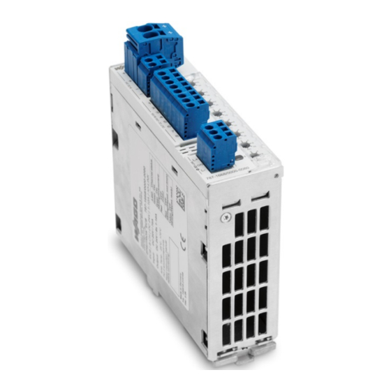
787-1668/0000-0080 Electronic Circuit Breaker Device Description The 787-1668/0000-0080 electronic circuit breaker reliably protects up to 8 load circuits against short circuiting and overloading. The 24 VDC input voltage applied to 8 output channels, each of which can be provided with separate fuse... -
Page 15: View
Device Description 787-1668/0000-0080 Electronic Circuit Breaker View Figure 1: View of device Table 5: Key for "Device view" figure Designation Reference Switch “Device Description” > “Operating Elements” > “Button” Rotary switch “Device Description” > “Operating Elements” > “Rotary Switch” Cover, sealable ®... -
Page 16: Connectors
Device Description 787-1668/0000-0080 Electronic Circuit Breaker Connectors Do not plug in or disconnect the female connector while a load is applied! Only plug in or disconnect the female connectors when the device is not live! Failure to observe this can result in damage to the contacts due to arcing! Plug the female connectors all the way into the male connectors! Always plug the female connectors all the way in to the male connectors. -
Page 17: Fuse-Protected Outputs
Device Description 787-1668/0000-0080 Electronic Circuit Breaker Total current exceeds 40 A! Distribute the current to input terminals "IN1" and "IN2" when the total current should exceed 40°A, as otherwise the plug-in connectors will become overheated and can be damaged or destroyed. -
Page 18: Display Elements
Device Description 787-1668/0000-0080 Electronic Circuit Breaker Display Elements A multi-colored LED, integrated in a button, is assigned to each channel. The LED indicates the current operating status of the channel. Figure 6: Display Elements Detailed Information on the Individual Operating Statuses The table below provides a brief overview of the individual button colors and corresponding meaning. -
Page 19: Operating Elements
Device Description 787-1668/0000-0080 Electronic Circuit Breaker Operating Elements 3.4.1 Button A button is assigned to each output channel. Depending on the operating mode the button can have two different functions: • During operation, the channel can be activated and de-activated. -
Page 20: Rotary Switch
Device Description 787-1668/0000-0080 Electronic Circuit Breaker 3.4.2 Rotary Switch A rotary switch, which can be used to set the trip current for the individual channel, is assigned to each channel. The following settings are possible: • • • • •... -
Page 21: Technical Data
Device Description 787-1668/0000-0080 Electronic Circuit Breaker Technical Data 3.5.1 Device Data Table 11: Device Data Width 42 mm Height 127 mm Height from upper-edge of DIN-rail 142.5 mm Weight 440 g Manual Version 1.1.0, valid from firmware 2.4.0... -
Page 22: Technical Data For "Input
Device Description 787-1668/0000-0080 Electronic Circuit Breaker 3.5.2 Technical Data for “Input" Table 12: Technical Data for “Input" Nominal input voltage 24 VDC Input voltage range 18 … 30 VDC Maximum residual ripple/ 3 % with resistive load ripple for the input voltage... -
Page 23: Technical Data For "Output
Device Description 787-1668/0000-0080 Electronic Circuit Breaker 3.5.3 Technical Data for “Output" Table 13: Technical Data for “Output" Nominal output voltage 8 × 24 VDC Trip current 1 A, 2 A, 3 A, 4 A, 6 A, 8 A, 10 A... -
Page 24: Technical Data For "Ambient Conditions
Device Description 787-1668/0000-0080 Electronic Circuit Breaker 3.5.4 Technical Data for “Ambient Conditions” Table 14: Technical Data for “Ambient Conditions” Ambient temperature range -25 °C … +70 °C Derating Maximum 10 A per channel Total output current (all channels) 50 A at 60 °C 40 A at 70 °C... -
Page 25: Approvals
Device Description 787-1668/0000-0080 Electronic Circuit Breaker Approvals The following approvals have been granted for the version 787-1668/0000-0080 of the electronic circuit breaker: Conformity Marking UL508 GL (Germanischer Lloyd) Cat. C (EMC 2) UL2367 Manual Version 1.1.0, valid from firmware 2.4.0... -
Page 26: Standards And Guidelines
Device Description 787-1668/0000-0080 Electronic Circuit Breaker Standards and Guidelines The 787-1668/0000-0080 electronic circuit breaker is in compliance with the following standards and guidelines: EU EMC Directive 2014/30/EU Information technology DIN EN 60950-1 + equipment – A11 + A1 + A12 Safety –... -
Page 27: Mounting
Mounting 787-1668/0000-0080 Electronic Circuit Breaker Mounting Mounting The device is designed for mounting on a DIN 35 rail. Mounting the Device on the DIN 35 Rail Figure 9: Mounting the device on the DIN 35 rail Tilt the device slightly. -
Page 28: Removing The Device From The Din 35 Rail
Mounting 787-1668/0000-0080 Electronic Circuit Breaker Removing the Device from the DIN 35 Rail Figure 11: Removing the device from the DIN 35 rail Use a screwdriver to press down on the locking tab. Figure 12: Removing the device from the DIN 35 rail Pull the device out at the bottom edge of the DIN 35 rail. -
Page 29: Connect Devices
Connect Devices 787-1668/0000-0080 Electronic Circuit Breaker Connect Devices Connection Example Figure 13: Connection Example Manual Version 1.1.0, valid from firmware 2.4.0... -
Page 30: Function Description
Function Description 787-1668/0000-0080 Electronic Circuit Breaker Function Description Undervoltage and Overvoltage Detection This device operates in a voltage range between 18 … 30 VDC. Tripping Characteristics Figure 14: Tripping Characteristics Manual Version 1.1.0, valid from firmware 2.4.0... -
Page 31: Activating Capacitive Loads
The tables below show experimentally determined reference values at an input voltage of 24 VDC and the maximum trip current: 6.3.1 Reference Values for 787-1668/0000-0080 Table 17: Reference Values for 787-1668/0000-0080 Line lengths Making capacity (µF) Making capacity (µF) Making capacity (µF) -
Page 32: General Operating Statuses
Function Description 787-1668/0000-0080 Electronic Circuit Breaker General Operating Statuses Table 18: General Operating Statuses Operating Status Status LED Button is pressed. Status 0: Initialization of the device (boot routine). Status 1: Green Status 4 Channel switched ON. Status 2: Status 4 Green, flashing Channel switched ON. -
Page 33: Figure 15: General Operating Statuses
Function Description 787-1668/0000-0080 Electronic Circuit Breaker Figure 15: General Operating Statuses Manual Version 1.1.0, valid from firmware 2.4.0... -
Page 34: On Delay For Specific Channels
Function Description 787-1668/0000-0080 Electronic Circuit Breaker ON Delay for Specific Channels The channels are activated in a staggered manner in the order of their channel numbers as soon as a minimum input voltage is present. All channels deactivated manually or by a reset signal are skipped in this process. -
Page 35: Status Query Via Channel 8" Function
Function Description 787-1668/0000-0080 Electronic Circuit Breaker “Status query via channel 8” Function Channel 8 has two different functions: “Fusing load circuits” function: • Analogous to channel 1 ... 7, channel 8 also protects load circuits against short circuits and overload. -
Page 36: Io-Link Interface
IO-Link Interface 787-1668/0000-0080 Electronic Circuit Breaker IO-Link Interface Cyclic Process Data The IO-Link interface can be used to receive or transfer process data. The individual input and output data are listed below in tabular form. 7.1.1 Output Data Direction of communication: Electronic circuit breaker → IO-Link Master The output data is 5 bytes. -
Page 37: Table 21: Bytes 3
IO-Link Interface 787-1668/0000-0080 Electronic Circuit Breaker Table 21: Bytes 3 … 5 – Configurable Data Byte 3 … 5 Description Bit 7 Bit 6 Bit 5 Bit 4 Bit 3 Bit 2 Bit 1 Bit 0 Status bits when selecting Channel 1 status messages (e.g.,... -
Page 38: Input Data
IO-Link Interface 787-1668/0000-0080 Electronic Circuit Breaker 7.1.2 Input Data Direction of communication: IO-Link Master → Electronic circuit breaker The input data is 3 bytes. • 1st byte: This byte contains the control commands for the electronic circuit breaker. A “0” means switch OFF; a “1” = switch ON/reset (depending on the actual status of the channel). - Page 39 IO-Link Interface 787-1668/0000-0080 Electronic Circuit Breaker Data Transfer It can take several process cycles for the data to be transferred. The confirmation byte indicates when the data has been transferred. Manual Version 1.1.0, valid from firmware 2.4.0...
-
Page 40: Table 25: Byte 3 - Validation Bits
IO-Link Interface 787-1668/0000-0080 Electronic Circuit Breaker Table 25: Byte 3 – Validation Bits Byte 3 Description Bit 7 Bit 6 Bit 5 Bit 4 Bit 3 Bit 2 Bit 1 Bit 0 Validation bit 1 (byte 3) Validation bit 2 (byte 4) - Page 41 IO-Link Interface 787-1668/0000-0080 Electronic Circuit Breaker Table 26: Possible Combinations for the Optional Process Data Byte 2 Byte 3 Byte 4 Byte 5 Binary Decimal Optional process data value value '1100.1000' Tripped thermal Tripped Hardware release Tripped Error '1100.1001' Warning Overload...
-
Page 42: Acyclic Data
IO-Link Interface 787-1668/0000-0080 Electronic Circuit Breaker Acyclic Data All data available in the device can be read via acyclic communication. All readable or adjustable data is listed below with its address and data type. Table 27: Overview of Acyclic Data... -
Page 43: Table 28: Status Query (Index 64)
IO-Link Interface 787-1668/0000-0080 Electronic Circuit Breaker The respective commands (see Table “Overview of Acyclic Data”) for adjustable data are listed below: Table 28: Status Query (Index 64) Value Function Comment Status query “OFF” Channel 8 has the functionality of the circuit breaker. -
Page 44: Table 33: Status Of The Electronic Circuit Breaker (Index 601
IO-Link Interface 787-1668/0000-0080 Electronic Circuit Breaker Table 33: Status of the Electronic Circuit Breaker (Index 601 … 608) Value Function Comment N.C. Not connected Switched OFF Switched OFF via interface Switched ON Switched ON Tripped Tripped Current > 90 % Load current >... -
Page 45: Iodd" Device Description File
The included “IODD” device description file can be used to set acyclic data. As an example, the configuration of the electronic circuit breaker in WAGO-I/O-CHECK is explained below. The display can vary depending on the control system selected. More information on the IODD file You can find more information on loading and handling the IODD file in the manual for the 750-657 Series I/O Module (“IO-Link Master”). -
Page 46: Identification" Menu Item
IO-Link Interface 787-1668/0000-0080 Electronic Circuit Breaker 7.3.1.1 “Identification” Menu Item Figure 16: “Identification” Menu Item You can find information on connected electronic circuit breakers in this menu item. Manual Version 1.1.0, valid from firmware 2.4.0... -
Page 47: Parameters" Menu Item
IO-Link Interface 787-1668/0000-0080 Electronic Circuit Breaker 7.3.1.2 “Parameters” Menu Item Figure 17: “Parameters” Menu Item The following parameters can be set in this menu item. Manual Version 1.1.0, valid from firmware 2.4.0... -
Page 48: Table 29: Configuration Process Data Bytes 3
IO-Link Interface 787-1668/0000-0080 Electronic Circuit Breaker Table 35: “Parameters” Menu Item Setting Option Description Threshold Critical Input Voltage The minimum and maximum values for the input voltage can be (Max/Min) entered. If the respective threshold value is exceeded or undershot, the device outputs a warning message. -
Page 49: Observation" Menu Item
IO-Link Interface 787-1668/0000-0080 Electronic Circuit Breaker 7.3.1.3 “Observation” Menu Item Figure 18: “Observation” Menu Item Current data can be called up for each channel in this menu item. The following is displayed: • “Channel Voltage” Display Field: The applied voltage is displayed for each channel. -
Page 50: Diagnosis" Menu Item
IO-Link Interface 787-1668/0000-0080 Electronic Circuit Breaker 7.3.1.4 “Diagnosis” Menu Item Figure 19: “Diagnosis” Menu Item Data for diagnostics is displayed. The trip counter can also be reset. Table 36: “Diagnosis” Menu Item Setting Option Description eBreaker Type The item number of the electronic circuit breaker is displayed. -
Page 51: Process Data" Menu Item
IO-Link Interface 787-1668/0000-0080 Electronic Circuit Breaker 7.3.1.5 “Process Data” Menu Item Figure 20: “Process Data” Menu Item Cyclic process data is displayed in this menu item. Table 37: “Process Data” Menu Item Setting Option Description Process Data In The status of input data is listed. -
Page 52: Process Data Structure" Menu Item
IO-Link Interface 787-1668/0000-0080 Electronic Circuit Breaker 7.3.1.6 “Process Data Structure” Menu Item Figure 21: “Process Data Structure” Menu Item The structure of cyclic process data is displayed in this menu item. Table 38: “Process Data Structure” Menu Item Setting Option... -
Page 53: Events" Menu Item
IO-Link Interface 787-1668/0000-0080 Electronic Circuit Breaker 7.3.1.7 “Events” Menu Item Figure 22: “Events” Menu Item Events that occur are displayed in this menu item. Manual Version 1.1.0, valid from firmware 2.4.0... -
Page 54: Info" Menu Item
IO-Link Interface 787-1668/0000-0080 Electronic Circuit Breaker 7.3.1.8 “Info” Menu Item Figure 23: “Info” Menu Item General information is displayed in this menu item. Manual Version 1.1.0, valid from firmware 2.4.0... -
Page 55: Connection Info" Menu Item
IO-Link Interface 787-1668/0000-0080 Electronic Circuit Breaker 7.3.1.9 “Connection Info” Menu Item Figure 24: “Connection Info” Menu Item The communication contacts of the IO-Link interface are displayed in this menu item. Manual Version 1.1.0, valid from firmware 2.4.0... -
Page 56: List Of Figures
List of Figures 787-1668/0000-0080 Electronic Circuit Breaker List of Figures Figure 1: View of device ..................15 Figure 2: 24 V input ....................16 Figure 3: 0 V input ....................16 Figure 4: Fuse-protected outputs Ch1 … Ch8 ............17 Figure 5: Communication Contacts ..............17 Figure 6: Display Elements.................18... -
Page 57: List Of Tables
Table 14: Technical Data for “Ambient Conditions” ..........24 Table 15: Technical Data for “Signaling”.............24 Table 16: Technical Data for “Communication”...........24 Table 17: Reference Values for 787-1668/0000-0080 ........31 Table 18: General Operating Statuses ...............32 Table 19: Byte 1 – Collective Messages for All Channels ........36 Table 20: Byte 2 –... - Page 58 WAGO Kontakttechnik GmbH & Co. KG Postfach 2880 • D - 32385 Minden Hansastraße 27 • D - 32423 Minden Phone: +49 571 887 – 0 Fax: +49 571 887 – 844169 E-Mail: info@wago.com Internet: www.wago.com...
Need help?
Do you have a question about the 787-1668/0000-0080 and is the answer not in the manual?
Questions and answers