Table of Contents
Advertisement
Pos : 2 /D okumentati on allgemein/Ei nband/Ei nband Fronts eite - H andbuc h; CI 2017; mit DocVariablen (Standar d) @ 28\mod_1486477502910_0.doc x @ 405388 @ @ 1
Manual
787-2861(/xxxx-xxxx)
Electronic Circuit Breaker
24 VDC, 0.5 ... 8 A
Version 1.3.1
Pos : 3 /Alle Serien (Allgemeine M odul e)/Rec htlic hes, Allgemei nes/Impressum für Standardhandbüc her - allg. Angaben, Ansc hriften, T elefonnummer n und E-Mail-Adres sen @ 3\mod_1219151118203_21.doc x @ 21060 @ @ 1
Advertisement
Chapters
Table of Contents

Related Manuals for WAGO 787-2861 Series


Summary of Contents for WAGO 787-2861 Series
- Page 1 Pos : 2 /D okumentati on allgemein/Ei nband/Ei nband Fronts eite - H andbuc h; CI 2017; mit DocVariablen (Standar d) @ 28\mod_1486477502910_0.doc x @ 405388 @ @ 1 Manual 787-2861(/xxxx-xxxx) Electronic Circuit Breaker 24 VDC, 0.5 ... 8 A Version 1.3.1 Pos : 3 /Alle Serien (Allgemeine M odul e)/Rec htlic hes, Allgemei nes/Impressum für Standardhandbüc her - allg.
- Page 2 We wish to point out that the software and hardware terms as well as the trademarks of companies used and/or mentioned in the present manual are generally protected by trademark or patent. WAGO is a registered trademark of WAGO Verwaltungsgesellschaft mbH. === Ende der Liste für T extmar ke Ei nband_vorne === Manual...
-
Page 3: Table Of Contents
Table of Contents 787-2861 Electronic Circuit Breaker Pos : 5 /D okumentati on allgemein/Verzeic hnisse/Inhalts verz eichnis - Ü berschrift oG und Verzei chnis @ 3\mod_1219151230875_21.doc x @ 21063 @ @ 1 Table of Contents Notes about this Documentation ............. 5 Validity of this Documentation.............. - Page 4 Table of Contents 787-2861 Electronic Circuit Breaker List of Tables ....................45 === Ende der Liste für T extmar ke Verzeic hnis_vor ne === Manual Version 1.3.1...
-
Page 5: Notes About This Documentation
Manual by third parties that violate pertinent copyright provisions is prohibited. Reproduction, translation, electronic and phototechnical filing/archiving (e.g., photocopying) as well as any amendments require the written consent of WAGO Kontakttechnik GmbH & Co. KG, Minden, Germany. Non-observance will involve the right to assert damage claims. Manual... - Page 6 Notes about this Documentation 787-2861 Electronic Circuit Breaker Pos : 13.3 /Dokumentation allgemei n/Glieder ungs elemente/---Seitenwechs el--- @ 3\mod_1221108045078_0.doc x @ 21810 @ @ 1 Manual Version 1.3.1...
-
Page 7: Symbols
Notes about this Documentation 787-2861 Electronic Circuit Breaker Pos : 13.4 /All e Seri en ( Allgemei ne Module)/Ü bers chriften/Ebene 2/Symbol e - Ü berschrift 2 @ 13\mod_1351068042408_21.doc x @ 105270 @ 2 @ 1 Symbols Pos : 13.5.1 /All e Serien ( Allgemei ne Module)/Sicherheits- und sons tige Hi nweis e/Gefahr/Gefahr: _War nung vor Pers onenschäden allgemei n_ - Erläuter ung @ 13\mod_1343309450020_21.doc x @ 101029 @ @ 1 Personal Injury! Indicates a high-risk, imminently hazardous situation which, if not avoided, will result in death or serious injury. - Page 8 Notes about this Documentation 787-2861 Electronic Circuit Breaker Additional Information: Refers to additional information which is not an integral part of this documentation (e.g., the Internet). Pos : 13.6 /Dokumentation allgemei n/Glieder ungs elemente/---Seitenwechs el--- @ 3\mod_1221108045078_0.doc x @ 21810 @ @ 1 Manual Version 1.3.1...
-
Page 9: Number Notation
Pos : 13.10 /Alle Serien (Allgemeine M odul e)/Rechtliches, Allgemeines/Sc hriftkonventi onen @ 3\mod_1221059521437_21.doc x @ 21714 @ @ 1 Table 3: Font Conventions Font Type Indicates italic Names of paths and data files are marked in italic-type. e.g.: C:\Program Files\WAGO Software Menu Menu items are marked in bold letters. e.g.: Save >... -
Page 10: Important Notes
2.1.1 Subject to Changes WAGO Kontakttechnik GmbH & Co. KG reserves the right to provide for any alterations or modifications. WAGO Kontakttechnik GmbH & Co. KG owns all rights arising from the granting of patents or from the legal protection of utility patents. -
Page 11: Technical Condition Of Specified Devices
These modules contain no parts that can be serviced or repaired by the user. The following actions will result in the exclusion of liability on the part of WAGO Kontakttechnik GmbH & Co. KG: •... -
Page 12: Safety Advice (Precautions)
Important Notes 787-2861 Electronic Circuit Breaker Pos : 16.9 /All e Seri en ( Allgemei ne Module)/Ü bers chriften/Ebene 2/Sic her hei tshi nweis e - Übersc hrift 2 @ 6\mod_1260180299987_21.doc x @ 46724 @ 2 @ 1 Safety Advice (Precautions) Pos : 16.10 /Alle Serien (Allgemeine M odul e)/Sic herheits- und sonstige Hinweis e/Ei nlei tung Sic herheits hinweise Har dwar e @ 6\mod_1260180170493_21.doc x @ 46720 @ @ 1 For installing and operating purposes of the relevant device to your system the following safety precautions shall be observed:... - Page 13 Control systems connected to the device may also be damaged! Return the defective device directly to WAGO. Pos : 16.18 /Serie 787 ( EPSITR ON)/Wichtige Erläuterungen/Sic herheits- und sonstige Hinweis e/Achtung/Achtung: Fr eischwi ngende Leiter enden durc h ei ne geeignete Z ugentlas tung abfangen! (ohne F ederleis te) @ 23\mod_1435643960160_21.doc x @ 184791 @ @ 1...
- Page 14 Important Notes 787-2861 Electronic Circuit Breaker Do not reverse the polarity of connection lines! Avoid reverse polarity of data and power supply lines, as this may damage the devices involved. Pos : 16.24 /Alle Serien (Allgemeine M odul e)/Sic herheits- und sonstige Hinweis e/Achtung/Ac htung: Elektr ostatis che Entladung vermei den! - DIN EN 61340- 5-1/- 3 @ 6\mod_1260181364729_21.doc x @ 46759 @ @ 1 Avoid electrostatic discharge! The devices are equipped with electronic components that may be destroyed by electrostatic discharge when touched.
-
Page 15: Device Description
Device Description 787-2861 Electronic Circuit Breaker Pos : 18 /All e Seri en (Allgemei ne Module)/Ü berschriften/Ebene 1/Gerätebes chr eibung - Ü berschrift 1 @ 3\mod_1233756084656_21.doc x @ 27096 @ 1 @ 1 Device Description Pos : 19.1 /Serie 787 (EPSITRON)/Ger ätebesc hrei bung/Bes chr eibung/Anwendung/Anwendung 787-2861 @ 23\mod_1435323488284_21.doc x @ 184666 @ @ 1 The 787-2861/0xx0-0000 electronic circuit breaker reliably protects load circuits against short circuiting and overloading. -
Page 16: Table 5: Definition Of Terms
Device Description 787-2861 Electronic Circuit Breaker Pos : 19.8 /Serie 787 (EPSITRON)/Ger ätebesc hrei bung/Bes chr eibung/Funkti on/Funktion 787-2861: Begriffs definiti onen @ 30\mod_1501165191261_21.doc x @ 456661 @ @ 1 The terms “switched ON” and “switched OFF”, as well as “tripped” are used in this manual. -
Page 17: View
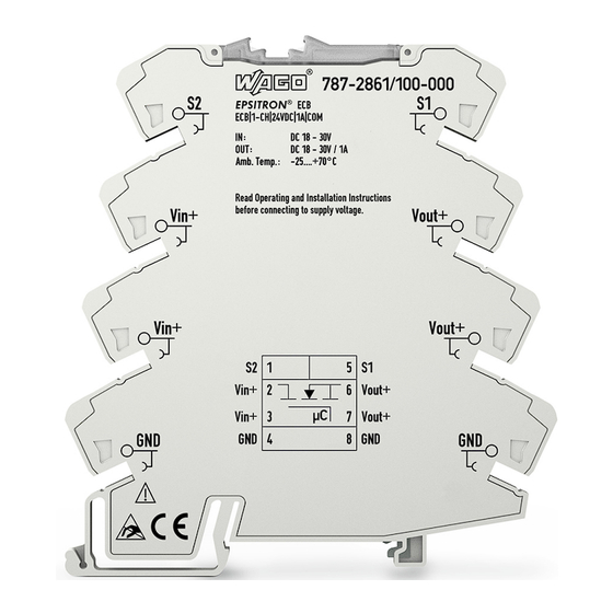
Device Description 787-2861 Electronic Circuit Breaker Pos : 21 /All e Seri en (Allgemei ne Module)/Ü berschriften/Ebene 2/Ansic ht - Ü berschrift 2 @ 4\mod_1240984217343_21.doc x @ 31958 @ 2 @ 1 View Pos : 22 /Serie 787 (EPSITRON)/Ger ätebesc hrei bung/Ansicht/Ansic ht 787- 2861 @ 23\mod_1435588017099_21.doc x @ 184765 @ @ 1 Figure 1: View Table 6: Legend for „View“... -
Page 18: Connectors
Device Description 787-2861 Electronic Circuit Breaker Pos : 24 /All e Seri en (Allgemei ne Module)/Ü berschriften/Ebene 2/Ansc hlüss e - Übersc hrift 2 @ 4\mod_1240984262656_21.doc x @ 31961 @ 2 @ 1 Connectors Pos : 25.1 /Serie 787 (EPSITRON)/Wic htige Erläuterungen/Sicher heits- und s ons tige Hi nweis e/Gefahr/Gefahr: Anschl üss e nicht unter Last ver drahten! @ 23\mod_1435643665495_21.doc x @ 184788 @ @ 1 Do not wire connections under load! The connections can be damaged or electric arcing can be caused by wiring the device under tension! -
Page 19: Display Elements
Device Description 787-2861 Electronic Circuit Breaker Pos : 27 /All e Seri en (Allgemei ne Module)/Ü berschriften/Ebene 2/Anzeig eel emente - Ü berschrift 2 @ 4\mod_1240984390875_21.doc x @ 31964 @ 2 @ 1 Display Elements Pos : 28 /Serie 787 (EPSITRON)/Ger ätebesc hrei bung/Anzeigeelemente/Anz eigeelemente 787-2861 @ 23\mod_1435670199178_21.doc x @ 184977 @ @ 1 The electronic circuit breaker has a status LED (d) and a configuration LED (e). -
Page 20: Operating Elements
Device Description 787-2861 Electronic Circuit Breaker Pos : 30 /All e Seri en (Allgemei ne Module)/Ü berschriften/Ebene 2/Bedi enel emente - Ü bers chrift 2 @ 4\mod_1239191655456_21.doc x @ 30439 @ 2 @ 1 Operating Elements Pos : 31 /Serie 787 (EPSITRON)/Ger ätebesc hrei bung/Bedi enelemente/Bedienel emente 787- 2861 @ 23\mod_1435670272611_21.doc x @ 184980 @ @ 1 The device can be operated and configured with the push and slide switch. -
Page 21: Technical Data
Device Description 787-2861 Electronic Circuit Breaker Pos : 33 /All e Seri en (Allgemei ne Module)/Ü berschriften/Ebene 2/Tec hnische D aten - Ü bersc hrift 2 @ 3\mod_1232967587687_21.doc x @ 26924 @ 2 @ 1 Technical Data Pos : 34.1 /Serie 787 (EPSITRON)/Ger ätebesc hrei bung/T ec hnisc he D aten/Angaben z um Ger ät/Gerätedaten 787-2861 (VS) @ 23\mod_1436339738014_21.doc x @ 185605 @ @ 1 Table 10: Device Dimensions (mm) W ×... -
Page 22: Table 12: Wiring
Device Description 787-2861 Electronic Circuit Breaker Feedback voltage Maximum 35 VDC Parallel connection Prohibited Series connection Prohibited Control input Control input Non-electrically isolated 24 VDC input (relative to the device 0 V input) Voltage level “active high”: minimum 18 VDC, maximum 30 VDC Voltage level “active low”: minimum -3 VDC, maximum 5 VDC Signal output... -
Page 23: Table 14: Mounting Positions And Ambient Temperatures
Device Description 787-2861 Electronic Circuit Breaker Pos : 34.6 /Serie 787 (EPSITRON)/Ger ätebesc hrei bung/T ec hnisc he D aten/Ei nbaulagen 787- 2861 @ 25\mod_1456235642409_21.doc x @ 202201 @ @ 1 Table 14: Mounting Positions and Ambient Temperatures Ambient temperature range Mounting position 0.5 A …... -
Page 24: Approvals
Device Description 787-2861 Electronic Circuit Breaker Pos : 36 /All e Seri en (Allgemei ne Module)/Ü berschriften/Ebene 2/Zul ass ung en - Übersc hrift 2 @ 3\mod_1224055364109_21.doc x @ 24030 @ 2 @ 1 Approvals Pos : 37.1 /Serie 787 (EPSITRON)/Ger ätebesc hrei bung/Z ulassungen/Z ulassungen Elektr. Sc hutzsc halter 787- xxxx Allgemein @ 23\mod_1436251532201_21.doc x @ 185368 @ @ 1 The following approvals have been granted for the 787-2861 electronic circuit breaker: Pos : 37.2 /All e Seri en ( Allgemei ne Module)/Z ulassungen/Standardz ulassungen/C E (Konformi täts kennz eichnung) @ 3\mod_1224494777421_21.doc x @ 24276 @ @ 1... -
Page 25: Standards And Guidelines
Device Description 787-2861 Electronic Circuit Breaker Pos : 39 /All e Seri en (Allgemei ne Module)/Ü berschriften/Ebene 2/Nor men und Richtlinien - Übersc hrift 2 @ 4\mod_1242804031875_21.doc x @ 33646 @ 2 @ 1 Standards and Guidelines Pos : 40.1 /Serie 787 (EPSITRON)/Ger ätebesc hrei bung/N or men und Ric htli nien/N ormen und Ric htli nien Elektronischer Schutzsc halter 787- xxxx, ohne Variantenangabe - Ei nlei tung @ 13\mod_1347452665951_21.doc x @ 102670 @ @ 1 The 787-2861 electronic circuit breaker is in compliance with the following standards and guidelines: Pos : 40.2 /All e Seri en ( Allgemei ne Module)/N or men und Ric htli nien/EMV-N ormen - Standar d/EU-EM V-Richtli nie 2014/30/EU @ 7\mod_1274262373820_21.doc x @ 56628 @ @ 1... -
Page 26: Function Description
Function Description 787-2861 Electronic Circuit Breaker Pos : 42 /All e Seri en (Allgemei ne Module)/Ü berschriften/Ebene 1/Funkti onsbesc hrei bung - Ü bersc hrift 1 @ 4\mod_1239025975389_21.doc x @ 30003 @ 1 @ 1 Function Description Pos : 43 /Serie 787 (EPSITRON)/F unkti ons besc hrei bung/Ausl ösekennlinien 787- 2861 @ 23\mod_1436253576227_21.doc x @ 185398 @ 2 @ 1 Tripping Characteristics The electronic circuit breaker verifies that the output current is greater than the nominal current setting. -
Page 27: Figure 4: Trip Characteristics
Function Description 787-2861 Electronic Circuit Breaker Figure 4: Trip Characteristics (with Trip Characteristic of a Circuit Breaker, Characteristic B) Pos : 44 /D okumentation allgemei n/Glieder ungs elemente/---Seitenwechs el--- @ 3\mod_1221108045078_0.doc x @ 21810 @ @ 1 Manual Version 1.3.1... -
Page 28: Undervoltage And Overvoltage Detection
Function Description 787-2861 Electronic Circuit Breaker Pos : 45 /Serie 787 (EPSITRON)/F unkti ons besc hrei bung/Unter- und Überspannungser kennung 787-2861 @ 25\mod_1456989794432_21.doc x @ 203158 @ 2 @ 1 Undervoltage and Overvoltage Detection The device only operates in a voltage range of 18 VDC … 30 VDC. A minimum voltage of 20 V is required to switch on the channel. -
Page 29: Activating Capacitive Loads
Function Description 787-2861 Electronic Circuit Breaker Pos : 47 /Serie 787 (EPSITRON)/F unkti ons besc hrei bung/Ei nsc hal ten von kapaziti ven Las ten 787- 2861 @ 23\mod_1436253830572_21.doc x @ 185401 @ 2 @ 1 Activating Capacitive Loads High capacitive loads can be applied using the electronic circuit breaker. The resulting high inrush currents strain the feeding power supply. -
Page 30: Control Input S1
Function Description 787-2861 Electronic Circuit Breaker Pos : 50 /Serie 787 (EPSITRON)/F unkti ons besc hrei bung/Steuerei ngang 787- 2861 @ 23\mod_1436260234505_21.doc x @ 185430 @ 2 @ 1 Control Input S1 A signal (18 V … 30 V) between the control input and GND allows the state of the electronic circuit breaker to be changed. -
Page 31: Signal Output S2
Function Description 787-2861 Electronic Circuit Breaker Pos : 53 /Serie 787 (EPSITRON)/F unkti ons besc hrei bung/Sig nal ausg ang 787- 2861 @ 23\mod_1436260372498_21.doc x @ 185433 @ 2 @ 1 Signal Output S2 The channel status can be queried at the signal output. This signal output is short-circuit-proof and has a common potential with the power supply ground. -
Page 32: Table 17: Signal Output S2 - Indicators 787-2861/0108-0020
Function Description 787-2861 Electronic Circuit Breaker Table 17: Signal Output S2 – Indicators 787-2861/0108-0020 Signal Output S2 Status Explanation Status LED Status 0: Initialization of the device (boot 24 V 24 V 24 V 24 V 24 V 24 V 24 V routine). -
Page 33: Mounting
Mounting 787-2861 Electronic Circuit Breaker Pos : 55 /All e Seri en (Allgemei ne Module)/Ü berschriften/Ebene 1/M onti eren - Ü bersc hrift 1 @ 3\mod_1225446744750_21.doc x @ 24900 @ 1 @ 1 Mounting Pos : 56.1 /All e Seri en ( Allgemei ne Module)/Sicherheits- und s ons tige Hi nweis e/Ac htung/Achtung: Elektros tatisc he Entladung ver mei den! - DIN EN 61340-5- 1/-3 @ 6\mod_1260181364729_21.doc x @ 46759 @ @ 1 Avoid electrostatic discharge! The devices are equipped with electronic components that may be destroyed by electrostatic discharge when touched. -
Page 34: Removal From The Din-Rail
Mounting 787-2861 Electronic Circuit Breaker 5.1.2 Removal from the DIN-Rail Figure 6: Removal To remove (see figure “Removal”), pull down the snap-in mounting foot (c) [1]. Use a screwdriver or an operating tool for this. Tilt the device forward [2] and unhook it from the DIN-rail. Pos : 57 /D okumentation allgemei n/Glieder ungs elemente/---Seitenwechs el--- @ 3\mod_1221108045078_0.doc x @ 21810 @ @ 1 Manual Version 1.3.1... -
Page 35: Connect Devices
Connect Devices 787-2861 Electronic Circuit Breaker Pos : 58 /All e Seri en (Allgemei ne Module)/Ü berschriften/Ebene 1/Geräte ansc hließ en - Übersc hrift 1 @ 3\mod_1234172889468_21.doc x @ 27460 @ 1 @ 1 Connect Devices Pos : 59 /Serie 787 (EPSITRON)/Wic htige Erläuterungen/Sic her heits- und s ons tige Hi nweis e/Gefahr/Gefahr: Anschl üss e nicht unter Last ver drahten! @ 23\mod_1435643665495_21.doc x @ 184788 @ @ 1 Do not wire connections under load! The connections can be damaged or electric arcing can be caused by wiring the device under tension! -
Page 36: Connection Example 787-2861/0108-0020
The resulting behavior for signal output S2 is described in section “Signal Output S2”, Table “Signal Output S2 – Indicators 787-2861/0108-0020”, column “External Relay Control”. WAGO offers the following relays for both versions: Table 18: Relay Item Number Description 857-304... -
Page 37: Figure 9: Connection Example 2 - 787-2861/0108-0020
Connect Devices 787-2861 Electronic Circuit Breaker Connection Example 2: Galvanic Isolation between Load Circuit and Input Potentials Figure 9: Connection Example 2 – 787-2861/0108-0020 In this version, two relays ensure that the load circuit is galvanically isolated from the input potentials if the device has tripped. Pos : 64 /D okumentation allgemei n/Glieder ungs elemente/---Seitenwechs el--- @ 3\mod_1221108045078_0.doc x @ 21810 @ @ 1 Manual Version 1.3.1... -
Page 38: Distribute Potential
Connect Devices 787-2861 Electronic Circuit Breaker Pos : 65 /Serie 787 (EPSITRON)/Ansc hließ en/Potential verteilen 787-2861 @ 25\mod_1456309570497_21.doc x @ 202387 @ 2 @ 1 Distribute Potential The devices have two connection points for the positive output (connections 6 and 7) and two connection points for the negative input/output (connections 4 and 8). -
Page 39: Bridging Voltage Or Signal
Connect Devices 787-2861 Electronic Circuit Breaker Pos : 67 /Serie 787 (EPSITRON)/Ansc hließ en/Brüc ken - 787- 2861 @ 25\mod_1455280178632_21.doc x @ 201525 @ 2 @ 1 Bridging Voltage or Signal Push-in type jumper bars can be used to distribute an applied voltage or signal to several 787-2861 electronic circuit breakers. -
Page 40: Configuration (787-2861/0108-0020 Only)
Configuration (787-2861/0108-0020 only) 787-2861 Electronic Circuit Breaker Pos : 69 /Serie 787 (EPSITRON)/Konfig urati on/Konfiguration 787- 2861/0108- 0020 @ 28\mod_1484055772703_21.doc x @ 402725 @ 1 @ 1 Configuration (787-2861/0108-0020 only) For this version, current level and signal output S2 can be configured from the push and slide switch. -
Page 41: Diagnostics
Diagnostics 787-2861 Electronic Circuit Breaker Pos : 71 /All e Seri en (Allgemei ne Module)/Ü berschriften/Ebene 1/Diagnos e - Ü bers chrift 1 @ 4\mod_1240831069471_21.doc x @ 31372 @ 1 @ 1 Diagnostics Pos : 72 /Serie 787 (EPSITRON)/F unkti ons besc hrei bung/Allgemeine Betriebsz ustände 787-2861 @ 23\mod_1436254565158_21.doc x @ 185404 @ 2 @ 1 General Operating Statuses Table 20: General Operating Statuses Operating Status... -
Page 42: Figure 12: General Operating Statuses
Diagnostics 787-2861 Electronic Circuit Breaker Figure 12: General Operating Statuses Manual Version 1.3.1... - Page 43 Diagnostics 787-2861 Electronic Circuit Breaker === Ende der Liste für T extmar ke Inhalt_mitte === Manual Version 1.3.1...
-
Page 44: List Of Figures
Pos : 74 /D okumentation allgemei n/Verz eic hniss e/Abbil dungs verz eic hnis - Übersc hrift oG und Verz eichnis @ 3\mod_1219222916765_21.doc x @ 21080 @ @ 1 List of Figures Figure 1: View ....................17 Figure 2: Connections ..................18 Figure 3: Display Elements.................19 Figure 4: Trip Characteristics (with Trip Characteristic of a Circuit Breaker, Characteristic B) ..................27... - Page 45 787-2861 Electronic Circuit Breaker Pos : 76 /D okumentation allgemei n/Verz eic hniss e/Tabell enverz eichnis - Übersc hrift oG und Verz eichnis @ 3\mod_1219222958703_21.doc x @ 21084 @ @ 1 List of Tables Table 1: Versions ....................5 Table 2: Number Notation ................... 9 Table 3: Font Conventions ..................
- Page 46 Pos : 79 /D okumentation allgemei n/Einband/Einband R üc ks eite - alle D okumente; CI 2017 @ 28\mod_1486477503580_21.doc x @ 405394 @ @ 1 WAGO Kontakttechnik GmbH & Co. KG Postfach 2880 • D - 32385 Minden Hansastraße 27 • D - 32423 Minden Phone: +49 571 887 –...
Need help?
Do you have a question about the 787-2861 Series and is the answer not in the manual?
Questions and answers