
Related Manuals for Hoshizaki HR24B


Summary of Contents for Hoshizaki HR24B
- Page 1 Service Manual Undercounter Refrigerator Models HR24B Number: 73229 hoshizakiamerica.com Issued: 3-6-2019...
- Page 2 Hoshizaki provides this manual primarily to assist qualified service technicians in the service of this appliance. Should the reader have any questions or concerns which have not been satisfactorily addressed, please call, send an e-mail message, or write to the Hoshizaki Technical Support Department for assistance. Phone: 1-800-233-1940; (770) 487-2331 Fax: 1-800-843-1056;...
-
Page 3: Table Of Contents
CONTENTS Important Safety Information ....................4 I. General Information ......................7 A. Construction ........................7 1. HR24B........................7 2. Dimensions and Storage Capacity ................8 B. Refrigeration Circuit....................... 9 II. Sequence of Operation and Service Diagnosis ............... 10 A. Sequence of Operation Flow Chart ................10 B. -
Page 4: Important Safety Information
Important Safety Information Throughout this manual, notices appear to bring your attention to situations which could result in death, serious injury, damage to the appliance, or damage to property. Indicates a hazardous situation that, if not avoided, will result in DANGER death or serious injury. - Page 5 • THE APPLIANCE MUST BE WARNING GROUNDED. The appliance is equipped The appliance should be destined only to with a NEMA 5-15 three-prong grounding the use for which it has been expressly plug to reduce the risk of potential conceived. Any other use should be shock hazards.
- Page 6 NOTICE WARNING, continued • Protect the floor when moving the • Children should be properly supervised appliance to prevent damage to the floor. around the appliance. • Keep ventilation openings, in the • Do not climb, stand, or hang on the appliance enclosure or in the built-in appliance or door or allow children or structure, clear of obstruction.
-
Page 7: General Information
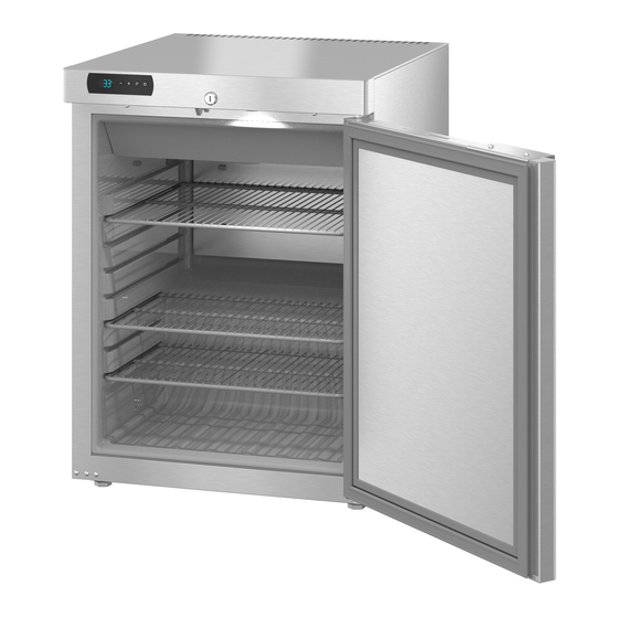
I. General Information A. Construction 1. HR24B Door Lock Door Switch Display Module/ Control Board Door • Evaporator Fan • Evaporator • Cabinet Thermistor Wire Shelves Door Gasket • Evaporator Fan Shroud Condenser Compressor Wire Harness Condensate Drain Line Power Cord... -
Page 8: Dimensions And Storage Capacity
Front View Side View Additional Dimensions (mm [in.]) Model Interior Width Interior Height Interior Depth Door Stay Open Position HR24B 460 [18 1/2] 475 [18 3/4] 450/330 [17 3/4 / 13] 616 [24 1/4] b) Storage Capacity Storage Capacity Interior Storage... -
Page 9: Refrigeration Circuit
B. Refrigeration Circuit Left Side Perimeter Liquid Line Condenser Drier Condensate Pan Evaporator Capillary Tube Evaporator Fan Motor Compressor... -
Page 10: Sequence Of Operation And Service Diagnosis
II. Sequence of Operation and Service Diagnosis A. Sequence of Operation Flow Chart... -
Page 11: Cabinet Temperature And Defrost
B. Cabinet Temperature and Defrost 1. Default Settings The default CT setpoint is 39°F. The default CT display scale setting is °F. NOTICE! Do not change the CT display scale from °F to °C. All temperature related values in the service menu must be changed manually if the CT display scale is changed from °F to °C. -
Page 12: Display Module Icons
C. Display Module Icons Display module icons inform you of energized components and if the appliance is in alarm. Display Module Icons Icon Meaning Compressor Steady: Compressor running. • Flashing: Compressor delay timer. Compressor starts within 2 min. • While adjusting cabinet temperature setpoint. For cabinet temperature setpoint adjustment, see "II.B Cabinet Temperature and Defrost."... -
Page 13: Service Diagnosis
E. Service Diagnosis Risque De Feu Ou D'Explosion DANGER Le Frigorigène Est Inflammable Risk of Fire or Explosion • Suivre attentivement les instructions Flammable Refrigerant Used de manipulation conformément à la • Follow handling instructions carefully réglementation gouvernementale. in compliance with U.S. government •... - Page 14 The diagnostic procedure is basically a sequence check that allows you to diagnose the electrical system and components. Before proceeding, check for correct installation and proper voltage per appliance nameplate. When checking AC voltage (115VAC), always choose a neutral (W) wire to establish a good neutral connection. If the control board is in alarm, see "II.I Alarm Safeties."...
- Page 15 9) Cool Down Achieved–EvapFM icon is on. CTh cools to setpoint (default 39°F). EvapFM continues. If Comp run time > 3-min., Comp icon turns off and Comp de-energizes. If Comp run time < 3-min., Comp continues until 3-min. Comp run timer terminates, then Comp icon turns off and Comp de-energizes. Diagnosis: If CTh is in range and Comp does not de-energize, confirm Comp run time >...
- Page 16 12) Energy Saving Mode ESM initiates during periods of inactivity. Once CTh cools to setpoint, 20-min. ESM timer starts. DS must remain engaged without activation (door open) for 20 min. after CTh has achieved setpoint for ESM to initiate. Once 20-min. ESM timer terminates, EvapFM operates on ESM cycle.
-
Page 17: Control Board And Display Module Check
F. Control Board and Display Module Check • For factory default settings, see "II.J. Service Menu." • For control board check procedure, see "II.F.3. Control Board Check." NOTICE • The control board and display module are fragile; handle very carefully. •... -
Page 18: Control Board Check
3. Control Board Check Before replacing a CB that does not show a visible defect and that you suspect is bad, always conduct the following check procedure. This procedure will help you verify your diagnosis. Always choose a neutral (W wire) to establish a good neutral connection when checking AC voltage (115VAC). -
Page 19: Thermistor Check
b) Defrost Termination: Comp icon is on. EvapFM icon flashing. 30-min. DT terminates. 6-hr. DT starts. Comp icon turns on and Comp energizes. 2-min. EvapFM timer starts. EvapFM icon starts flashing and EvapFM de-energizes. When 2-min. EvapFM timer terminates, EvapFM icon turns steady and EvapFM energizes. Normal operation resumes. -
Page 20: Diagnostic Chart
H. Diagnostic Chart Before consulting the diagnostic charts, check the following: • Check the cabinet temperature setpoint and factory default settings. For factory default settings, see "II.B. Cabinet Temperature and Defrost" and "II.J. Service Menu." • Make sure the doors are not left open or opened too often and that they are sealing properly. - Page 21 2. Evaporator is Frozen Up Evaporator is Frozen Up - Possible Cause Evaporator a) Dirty. Evaporator Fan Motor a) Defective. Control Board a) Defective, not operating evaporator fan motor. Refrigerant/Refrigerant Lines a) Gas leak, low charge. b) Refrigerant lines restricted. 3.
-
Page 22: Alarm Safeties
I. Alarm Safeties The alarms are designed to protect the appliance and the items inside. These alarms give information and warnings in the event the appliance is operating out of acceptable parameters. For all alarms except Pr1, the alarm icon turns on and the alarm code alternates with the cabinet temperature. -
Page 23: Service Menu
b) Clearing High and Low Temperature Alarms To clear an alarm, follow the steps below. 1) Press the "-" button for 3 sec. to enter the alarm menu. "EnS" is displayed. 2) Press the "-" or "+" button twice. After pressing the "-" or "+" button the first time, "LS" is displayed. - Page 24 b) Service Menu Chart Setpoint Service Menu Min. Max. Unit Factory Setting Description See r1 See r2 °C/°F 39°F Cabinet setpoint. (compressor off temperature). (see r0 for compressor on temperature). Thermistor Input (Do Not Adjust) Service Menu Min. Max. Unit Factory Setting Description °C/°F...
- Page 25 Defrost (Do Not Adjust) Service Menu Min. Max. Unit Factory Setting Description hrs. Defrost interval: 0=no defrost Defrost type. Do not adjust. 0=electric heater 1=hot gas 2=off cycle (evaporator fan motor) °C/°F Limit for defrost if P3 = 1 or 2. min.
- Page 26 Temperature Alarm (Do Not Adjust) Service Menu Min. Max. Unit Factory Setting Description AL alarm sensor. Do not adjust. 0=cabinet thermistor 1=evaporator thermistor °C/°F Degrees below setpoint for AL alarm when A2=1. Do not adjust. AL alarm. Do not adjust. 0=deactivated 1=A1 relative to setpoint (setpoint - A1)
- Page 27 Evaporator Fan Motor (Do Not Adjust) Service Menu Min. Max. Unit Factory Setting Description Fan operation with door closed. Do not adjust. 0=off 1=on: see also F13, F14, and L10 2=parallel with compressor 3= dependent on F1 4=disabled when compressor is off, dependent on F1 when compressor is on.
- Page 28 Door Switch and Door Alarm (Do Not Adjust) Service Menu Min. Max. Unit Factory Setting Description Door switch function. 1=compressor and evaporator fan motor de-energized 2=evaporator fan motor de-energized 3-5=reserved Door switch operation. 0=normally open 1=normally closed min. Door alarm time delay. -1=deactivated min.
-
Page 29: Refrigeration Circuit And Component Service Information
III. Refrigeration Circuit and Component Service Information DANGER Risk of Fire or Explosion Flammable Refrigerant Used • Follow handling instructions carefully in compliance with U.S. government regulations. • Do not use mechanical devices to defrost. • Do not puncture refrigerant tubing. Risk of fire or explosion due to puncture of refrigerant tubing;... - Page 30 WARNING • Wear appropriate personal protective equipment (PPE) when servicing the appliance. • Technician must utilize a combustible gas leak detector at all times. • Notify everyone in the immediate area that you are working with flammable refrigerant. • Do not work on appliance in a confined space. Confirm area is well ventilated. •...
-
Page 31: Refrigeration Circuit Service Information
A. Refrigeration Circuit Service Information WARNING • Repairs requiring the refrigeration circuit to be opened must be performed by properly trained and EPA-certified service personnel. • Use an electronic leak detector or soap bubbles to check for leaks. Add a trace of refrigerant to the system (if using an electronic leak detector), and then raise the pressure using nitrogen gas (140 PSIG). - Page 32 2. Brazing DANGER Risk of Fire or Explosion Flammable Refrigerant Used • Servicing shall be done by factory authorized service personnel to minimize the risk of possible ignition due to incorrect parts or improper service. Risque De Feu Ou D'Explosion Le Frigorigène Est Inflammable •...
- Page 33 5) Disconnect the gauge manifold hose from the vacuum pump and attach it to a refrigerant service cylinder. Remember to loosen the connection and purge the air from the hose. For the required refrigerant charge, see the nameplate. Hoshizaki recommends only virgin or reclaimed refrigerant which meets ARI Standard 700 (latest edition) be used.
-
Page 34: Component Service Information
B. Component Service Information NOTICE When replacing a component listed below, see the notes to help ensure proper operation. Component Notes Install a new PTC relay. WARNING! To reduce the risk of electric shock, be sure to Compressor reconnect the component's ground wire. C. -
Page 35: Cleaning And Maintenance Instructions
IV. Cleaning and Maintenance Instructions A. Cleaning WARNING • Before cleaning the appliance, turn off and unplug the appliance to prevent electric shock by unexpected entrance of water into the appliance or injury by moving parts. • Before cleaning the appliance, move all items into another refrigerator. •... -
Page 36: Preparing The Appliance For Periods Of Non-Use
V. Preparing the Appliance for Periods of Non-Use When shutting down the appliance for more than one week, follow the instructions below. WARNING Prevent the doors from closing to reduce the risk of children getting trapped. IMPORTANT Clean the cabinet interior, door gaskets, and shelves. 1) Before shutting down the appliance, move all items into another refrigerator. -
Page 37: Disposal
VI. Disposal DANGER Risk of Fire or Explosion Flammable Refrigerant Used • Follow handling instructions carefully in compliance with U.S. government regulations. • Do not puncture refrigerant tubing. Risk of fire or explosion due to puncture of refrigerant tubing; follow handling instructions carefully. •... -
Page 38: Technical Information
We reserve the right to make changes in specifications and design without prior notice. A. Electrical and Refrigerant Data See the nameplate for electrical and refrigerant data. The nameplate is located inside the cabinet. Electrical and Refrigerant Data Design Pressure (PSIG) Refrigerant (oz.) Model AC Supply Voltage Amperes HIGH R-600a HR24B 115/60/1 2.80... -
Page 39: Wiring Diagram
B. Wiring Diagram...
Need help?
Do you have a question about the HR24B and is the answer not in the manual?
Questions and answers