
Subscribe to Our Youtube Channel
Related Manuals for Hoshizaki HRFW-77MS4


Summary of Contents for Hoshizaki HRFW-77MS4
- Page 1 Date 03-10-16 Rev No DOC NO RBC/SM/03-10- COMMERCIAL REFRIGERATOR FREEZER HRFW-77MS4...
-
Page 2: Table Of Contents
Table of Contents: CONTENT PAGE NO Safety Instructions Product Indent Use Dimension Layout Technical Specification Procedure to open the Canopy Procedure to replace the Evaporator fan motor Procedure to replace the Dew Collector Procedure to replace the Defrost Heater Procedure to replace the Defrost Sensor Procedure to replace the Appliance Sensor Procedure to replace the Condenser Fan Motor Procedure to replace the Carel Controller... -
Page 3: Safety Instructions
Safety instructions: The following instructions contain important safety precautions an should be strictly observed WARNING: There is a possibility of death or serious injury to the service person and a third party or the user due to improper service operations or defects in serviced products. - Page 4 4) When unbrazing the refrigeration circuit connections, check that the circuit is completely evacuated. The refrigerant may produce a poisonous gas when coming in contact with an open flame. 5) Do not braze in an enclosed room to prevent carbon monoxide poisoning . 6) In case of a refrigerant leak, locate and repair the leaking part completely before recharging the refrigerant and checking for further leaks.
-
Page 5: Product Indent Use
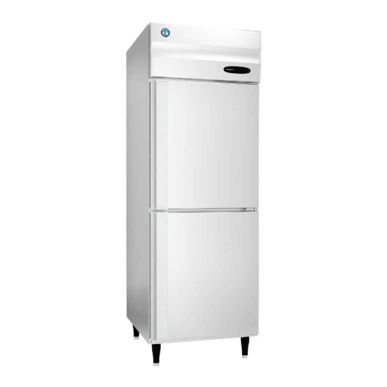
HRFW-77 is two door Combi model. It uses electronic temperature controller, R404A as refrigerant, CFC free insulation and are classified climatic class T (5) i.e. Ambient 40°C and 40% RH Nomenclature H – Hoshizaki R – Refrigerator F – Freezer W– Made by Western Refrigeration... -
Page 6: Dimension Layout
DIMENSIONAL LAYOUT :... - Page 7 INSTALLATION REQUIREMENTS: LOCATION: For best operating results, 1) The freezer should not be located next to ovens, grills and other high heat producing equipments. 2) The location should provide a firm foundation for the equipments. 3) Avoid a site where dripping is not allowed. Especially a side by side , back to back installation.
- Page 8 SET UP: 1) Cut the vinyl shipping tape and remove the carton 2) Take out the accessory shelves, shelf clips and legs. Attach the four shelf clips horizontally to the shelf posts. Place the shelf’s on the shelf clips. 3) Remove the two bolts on the bottom of the unit. 4) Turn the unit 90 degrees on the pallet, tilt the unit sideways, and screw in the two adjustable legs.
-
Page 9: Technical Specification
TECHNICAL SPECIFICATIONS: HFW-77 PARAMETERS DETAILS HRFW-77MS4 Model name Freezer : 305 Liters Gross volume Refrigerator : 305 Liters Freezer : 277 Liters Net volume Refrigerator : 286 Liters Freezer: -16°C to -23°C Temperature setting range Refrigerator: -2°C to 12°C (operation range - not adjustable) 01 hour 56 mins @ 40.6°C ambient... - Page 10 Solid swing door/ SS 430 2B hair line Door type / Door frame / type of No. 4 finished / integrated handle / section / number of doors 2 number 15 Door Switch 16 Door external dimension (mm) 676.5 (W) x 760 (H) Type of wheels / legs / qty.
-
Page 11: Procedure To Open The Canopy
PROEDURE TO OPEN THE CANOPY: Step 1: Catch the canopy on both sides at the bottom Step 2: After that pull canopy on your side, the locks will release at bottom as shown in figure Step 3: Then remove the canopy by lifting it up as shown in figure After removing the canopy we can get the access to machine room for service. -
Page 12: Procedure To Replace The Evaporator Fan Motor
PROCEDURE TO REPLACE EVAPORATOR FAN MOTOR:... - Page 13 INDEX SAP CODE DESCRIPTION 1107300 EVAP FAN MOTOR BRACKET MOTOR 10W – 1503912 ELCO(NET4T10ZVN022) 1502215 WASHER W6 SUS 1502114 SCREW + N4 X 8 SUS 1500876 IMPELLER 5 X 8 " V34 DEG SUPPLIED WITH MOTOR WASHER MOTOR SUPPLIED WITH MOTOR SCREW MOTOR...
-
Page 14: Procedure To Replace The Dew Collector
PROCEDURE TO REPLACE DEW COLLECTOR HEATER:... -
Page 16: Procedure To Replace The Appliance Sensor
PROCEDURE TO REPLACE CONDENSER FAN MOTOR:... -
Page 17: Procedure To Replace The Carel Controller
HOW TO ENTER INTO THE CONTROLLER PERAMETERS: 1) Open front panel 2) Press the set key for 3 seconds. The screen displays the PS menu. Press the set button again, the screen displays zero, use up and down key to input the password 22. - Page 19 HRFW POWER BOX: SR.NO. SAP CODE DESCRIPTION LEG CONTROL BOX 1107867 SCREW TAPTITE M4X8 - 445994-05 1508312 CONTROL BOX COVER 1107293 2 WAY MALE PLUG (5559-02P) 1501045 DIGITAL TEMPERATURE METER SF-130A 1507589 SUS CONNECTOR LABEL FREEZER SUS SENSOR LABEL FREEZER CAUTION STICKER EARTHING 1510404 CAUTION STICKER HIGH VOLTAGE...
-
Page 20: Procedure To Replace The Door Switch
PROCEDURE TO REPLACE DOOR SWITCH: Fig-1 Fig-2 Remove the canopy from the front side. Unmount the door switch from the power box & take out the connector through the hinge as shown in Fig-1 Adopt the procedure vice versa for assembling. -
Page 21: Procedure To Replace The Door Gasket
PROCEDURE TO REPLACE DOOR GASKET: PROCEDURE TO REPLACE DOOR ASSEMBLY:... - Page 22 CAREL CONTROLER PROGRAM: CAREL PJEZC0P000 ELECTRONIC TEMPERATURE CONTROLLER PARAMETER SETTINGS FOR Revision HFW MODELS Date Display Parameters Min. Max. Factory HRFW- setting 77MS4 controller PASSWORD Control temperature ºC/ºF Mesurment stability Select Probe / input displayed (*) Select °C / °F (0=°C, 1=°F) Disable decimal point Preobe calibration 12.7...
-
Page 23: Carel Controller Programming
Defrost when the instrument switch on (1=activated) Defrost delay on start-up or from digital input Disable temperature display during defrost (1=display disabled) Dripping time after defrost Alarm bypass time after defrost Defrost priority over comp. protecttors (0=protection time respected; 1=protesction time not respected) Display defrost probe temp. -
Page 25: Wiring Drawings
Wiring Drawing:... -
Page 26: Trouble Shooting
Trouble Shooting:... -
Page 28: Disposal
DISPOSAL:...
Need help?
Do you have a question about the HRFW-77MS4 and is the answer not in the manual?
Questions and answers