
Related Manuals for Sega Bass Fishing STD


Summary of Contents for Sega Bass Fishing STD
- Page 1 1ST PRINTING JULY-1998 OWNER’S MANUAL STD VERSION SEGA ENTERPRISES, USA MANUAL NO. 4201-6394-01...
- Page 2 Warranty Your new Sega Product is covered for a period of 90 days from the date of shipment. This certifies that the Printed Circuit Boards, Power Supplies and Monitor are to be free of defects in workman- ship or materials under normal operating conditions. This also certifies that all Interactive Control Assemblies are to be free from defects in workmanship and materials under normal operating condi- tions.
-
Page 3: Table Of Contents
TABLE OF CONTENTS INTRODUCTION OF THE OWNERS MANUAL GENERAL PRECAUTIONS 1. PRECAUTIONS TO BE HEEDED FOR OPERATION 2. NAME OF PARTS 3. ACCESSORIES 8~12 4. ASSEMBLY AND INSTALLATION 5. PRECAUTIONS TO BE HEEDED WHEN MOVING MACHINE 14~22 6. CONTENTS OF GAME 7. -
Page 4: Introduction Of The Owners Manual
29” 3-mode scan display INTRODUCTION OF THE OWNERS MANUAL SEGA ENTERPRISES, LTD., has for more than 30 years been supplying various innovative and popular amusement products to the world market. This Owners Manual is intended to provide detailed descriptions together with all the necessary installation, game settings and parts ordering information related to the SEGA BASS FISHING U/R, a new SEGA product. -
Page 5: General Precautions 2~3
General Precautions Follow Instructions: All operating and use instructions should be followed. Attachments: Do not use attachments not recommended by the product manufacturer as they may cause hazards. Accessories: Do not place this product on an unstable cart, stand, tripod, bracket, or table. The product may fall, causing serious injury to a child or adult, and serious damage to the product. - Page 6 Safety Check: Upon completion of any service or repairs to this product, ask the service technician to perform safety checks to determine that the product is in proper operating condition. Heat: The product should be situated away from heat sources such as radiators, heat registers, stoves, or other prod- ucts (including amplifiers) that produce heat.
-
Page 7: Precautions To Be Heeded For Operation
1 . PRECAUTIONS TO BE HEEDED FOR OPERATION In order to prevent accidents, be sure to comply with the following points before and during operation. PRECAUTIONS TO BE HEEDED FOR OPERATION BEFORE STARTING THE OPERATION In order to avoid accidents, check the following before starting the operation: Check if all of the adjusters are in contact with the surface. -
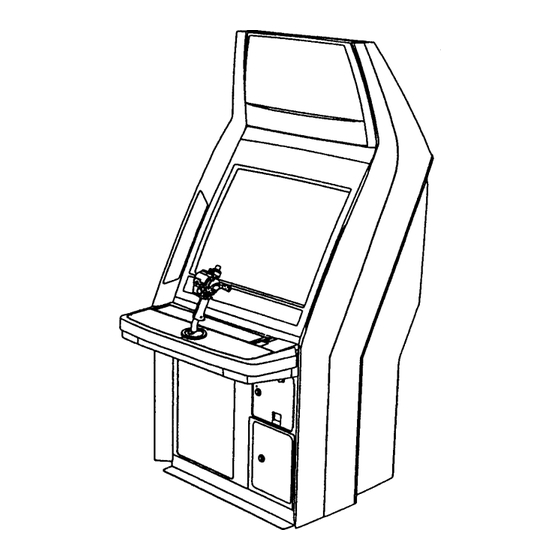
Page 8: Name Of Parts
2 . NAME OF PARTS WEIGHT WIDTH LENGTH HEIGHT GAME SPECIFICATIONS All measurements are in inches WHEN ASSEMBLED 30” 37” 65” 223 LBS. -
Page 9: Accessories
3 . ACCESSORIES... - Page 10 THE SHIPMENT METHOD DESCRIBED BELOW ONLY APPLIES TO ‘MODEL 3’ BOARDS CONTAINED IN THE FOLLOWING GAMES: SEGA BASS FISHING LOST WORLD, VIRTUA FIGHTER 3, SUPER GT, , STRIKER 2, DAYTONA 2, RALLY, HARELY DAVIDSON !!NEVER SHIP MODEL 3 GAME BOARDS...
-
Page 11: Assembly And Installation
4 . ASSEMBLING AND INSTALLATION Assembling should be performed as per this manual. Since this is a complex machine, erroneous assembling may cause damage to the machine, or malfunctioning to occur. When assembling, be sure to perform work by plural persons. Depending on the assembly work, there are some cases in which performing the work by a single person can cause personal injury or parts damage. - Page 12 SECURING IN PLACE (ADJUSTER ADJUSTMENT) Be sure to have all the Adjusters make contact with the surface. Un- less the Adjusters come into contact with the surface, the Cabinet can move of itself, causing an accident. This machine has 2 each of casters and adjusters (shown below). When the installation position is determined, cause the adjusters to come into contact with the floor directly, make adjustments in a manner so that the casters will be raised approximately 5mm.
- Page 13 POWER SUPPLY Ensure that the power cord is not exposed on the surface (passage, etc.). If exposed, they can be caught and are susceptible to damage. If damaged, the cord can cause an electric shock or short circuit. Ensure that the wiring position is not in the customer's passage way or the wiring has protective covering.
- Page 14 ASSEMBLING CHECK The TEST MENU allows for each part of the cabinet to be checked, the Monitor to be adjusted, and the coin and game related various functions to be performed. CPU ROM TEST Selecting the MEMORY TEST on the test mode menu screen GOOD (CROM03 BANK) IC.1...
- Page 15 SOUND TEST In the TEST mode, selecting SOUND TEST causes the screen, on which sound related BD and wiring connec- ( 0 ) tions are tested, to be displayed. be sure to check if the sound is satisfactorily emitted from each of speaker and the sound volume is appropriate.
-
Page 16: Precautions To Be Heeded When Moving Machine
5 . PRECATIONS TO BE HEEDED WHEN MOVING THE MACHINE When moving the machine, be sure to pull out the plug from the power supply. Moving the machine with the plug as is inserted can damage the power cord and cause a fire or elec- tric shock. -
Page 17: Contents Of Game
6 . CONTENTS OF GAME The following are operations and responses obtained when the machine functions satisfactorily. Any functioning different from the following may have been caused by a certain fault. Immediately investigate and eliminate the cause of malfunctioning to ensure satisfactory operation. HOW TO PLAY The ADVERTISE mode appearing on the screen before game play is comprised of the following: In this game, satisfying the condition of “CLEAR WEIGHT”... - Page 18 Insert a coin(s). Up to 9 credits can be counted at one time. Coins inserted after counting 9 credits will neither be counted nor returned. Select a Fishing area from among the 3 Areas of Lake Paradise (a virtual lake). Choose with SELECT LEVER and decide by START/CAST button.
- Page 19 SPINNER BAIT (EASY) Attract bass with this bait while reeling at a constant speed, or stopping to reel sometimes to allow for blade glistening. DEEP CRANK (EASY) This type is used for deep water. Have the lure hit the bottom and reel, then repeat real and stop action. SHALLOW CRANK (EASY) This is used for shallow water.
- Page 20 VIBRATION (EASY) Attract bass by reeling at the constant speed or having the lure hit an obstacle such as a stone, driftwood, etc. to cause irregular movements. MINNOW/ JERK BAIT (NORMAL) Attract bass by reeling at a constant speed and jerking the rod to reel so that the lure will look like a small fish making a quick escape.
- Page 21 Try to master the best lure and the most appropriate action to catch a big fish.
- Page 22 After the lure is decided, set the CAST spot (where to cast the lure). Select with the SELECT LEVER and decide by START/CAST button. Press the START/CAST button to have the lure cast automatically (at this time the player does not have to do the cast movement). Having its own territory, a big fish is hiding at a certain point in each area depending on the time zone and water temperatures.
- Page 23 When the lure hits the surface, turn the reel handle, move the rod, and activate the lure to attract bass. When bass snaps at the lure, pull the rod towards you by hooking up. For timely hooking..FISH! is displayed. For untimely hooking..MISS! is displayed. For a successful hooking, HIT BONUS time is added depending on the size of the hit bass.
- Page 24 When the bass is hooked, pull it towards you by paying attention to LINE TENSION METER.
- Page 25 7 When the bass is fished up, the following 5-step display &WEIGHT to be added to the total weight are shown. Then, BONUS TIME is added depending on the weight of the bass. SMALL ONE MEDIUM BIG ONE SUPER BIG RECORD SIZE If the total wieght exceeds the Norm weight, the player can proceed to the next Area.
-
Page 26: Explanation Of Test And Data Display
7 . EXPLANATION OF TEST AND DATA DISPLAY By operating the switch unit, periodically perform the tests and data check. When installing the machine initially or collecting cash, or when the machine does not function correctly, perform checking in accordance with the explanations given in this section. The following shows tests and modes that should be utilized as applicable. -
Page 27: Coin Meter, Internal Switches, And Switch Unit
7 - 1 COIN METER, INTERNAL SWITCHES, AND SWITCH UNIT COIN METER If the COIN METER and the Game Board are electronically discon- nected, game play is not possible. Do not touch places other than those specified. Touching places other than those specified can cause an electric shock or short circuit accident. - Page 28 SWITCH UNIT Never touch places other than those specified. Touching places not specified can cause electric shock and short circuit. Adjust to the optimum sound volume by considering the environmental requirements of the installation location. If the COIN METER and the game board are electrically disconnected, game play is not possible.
- Page 29 DOOR SWITCH When the service door is removed, the door switch functions to turn power off automatically. To turn power on the with the service door as is removed, use the accessory Cheater as per the (1)-(2) proce- dure below.
-
Page 30: Test Mode
7 - 2 TEST MODE This mainly checks if the operation of the game BD is accurate, and allows for COIN ASSIGNMENTS/GAME ASSIGNMENTS setting and Projector adjustments. TEST MENU Push the TEST BUTTON to cause the follow- CPU MEMORY TEST ing TEST MENU to appear: VIDEO MEMORYTEST BOUNDRY SCAN TEST... -
Page 31: Video Memory Test
7 - 4 VIDEO MEMORY TEST VIDEO BOARD ROM TEST This allows the functioning of the VIDEO GOOD (VROM01) IC.26 ***** MEMORY IC’s on the IC board to be checked. GOOD (CROM00) IC.27 ***** GOOD (CROM03) IC.28 ***** “GOOD” is displayed for normal IC’s and “BAD” GOOD (CROM02) IC.29... -
Page 32: Input Test
7 - 6 INPUT TEST This test mode displays the status of each switch, button, and Volu me. When the switch/button corrsponds to the name of the item is pressed, if OFF changes to ON, it is INPUT TEST satisfactory. When corresponding Volume is operated, if the Volume CAST value differs in a natural manner, it is satisfactory. -
Page 33: Test
7 - 9 C.R.T. TEST C.R.T. TEST 1/2 1 2 3 4 5 6 7 8 9 0 1 2 3 4 5 6 7 8 9 0 1 2 3 4 5 6 7 8 9 0 1 2 1 2 3 4 5 6 7 8 9 0 1 2 1 2 3 4 5 6 7 8 9 0 1 2 3 4 5 6 7 8 9 0 1 2 3 4 5 6 7 8 9 0 1 2 1 2 3 4 5 6 7 8 9 0 1 2 1 2 3 4 5 6 7 8 9 0 1 2 3 4 5 6 7 8 9 0 1 2 3 4 5 6 7 8 9 0 1 2 1 2 3 4 5 6 7 8 9 0 1 2 1 2 3 4 5 6 7 8 9 0 1 2 3 4 5 6 7 8 9 0 1 2 3 4 5 6 7 8 9 0 1 2 1 2 3 4 5 6 7 8 9 0 1 2... -
Page 34: Game Assignments
7 - 11 GAME ASSIGNMENTS Selecting the GAME ASSIGNMENTS in the MENU mode causes the present game settings to be displayed and also the game settings changes (game difficulty, etc.) can be made. Each item displays the following content. SETTING CHANGE PROCEDURE Setting changes cannot be stored unless the TEST BUTTON is pressed while the arrow is on EXIT. -
Page 35: Coin Assignments
7 - 12 COIN ASSIGNMENTS The “COIN ASSIGNMENTS” mode permits you to set the start number of credits, as well as the basic numbers of coins and credits. This mode expresses “how many coins correspond to how many credits.” SETTING CHANGE PROCEDURE Setting changes cannot be stored unless the TEST BUTTON is pressed while the arrow is on EXIT. - Page 36 TABLE 7.12a COIN/CREDIT SETTING (COIN CHUTE COMMON TYPE) SETTING FUNCTIONING OF CHUTE#1 SETTING #1 1 COIN 1 CREDIT SETTING #2 1 COIN 2 CREDITS SETTING #3 1 COIN 3 CREDITS SETTING #4 1 COIN 4 CREDITS SETTING #5 1 COIN 5 CREDITS SETTING #6 1 COIN...
- Page 37 MANUAL SETTING Selecting MANUAL SETTING in the COIN ASSIGNMENTS mode displays the following screen. MANUAL SETTING COIN TO CREDIT 1 COIN 1 CREDIT BONUS ADDER NO BONUS ADDER COIN CHUTE #1 MULTIPLIER 1 COIN COUNTS AS 1 COIN COIN CREDIT COIN CHUTE #2 MULTIPLIER 1 COIN COUNTS AS 1 COIN COIN...
-
Page 38: Volume Setting
7 - 13 VOLUME SETTING This allows Slide Volume to be set. VOLUME SETTING Settings of volumes, etc., can be executed. Volume setting AUTO SETTING has 2 catagories, i.e., AUTO SETTING and MANUAL SETTING. AUTO SETTING performs the setting of the PULL POSITION MAX dd (df) MIN 74 (75) SWING POSITION... -
Page 39: Bookkeeping
7 - 14 BOOKKEEPING Choosing BOOKKEEPING in the MENU mode displays the data of operating status up to the present are shown on 2 pages. Press the TEST BUTTON to proceed to PAGE 2/2. COIN CHUTE#*: BOOKKEEPING PAGE1/2 Number of coins put in each Coin Chute. COIN REPORT COIN CHUTE #1 XXXXXXXXXXX... -
Page 40: Control Panel
8 . CONTROL PANEL In order to prevent an electric shock and short circuit, be sure to turn power off before performing work by touching the interior parts of the product. Be careful so as not to damage wirings. Damaged wiring can cause an electric shock or short circuit accident. -
Page 41: Replacing The Extension Spring 38~39
As shown in the PHOTO, insert the Spray Grease Nozzle to the inside of Guide plate and apply grease to the sliding friction portions of the part. 8 - 2 REPLACING THE EXTENSION SPRING In the case the centering action (to return to the center position) of the reel (rod) is inactive, the cause may be the secular change of or damage to Extension Spring and Torsion Spring. - Page 42 Take out the 34 screws and remove 3 By using the narrow-edged flat the Guide Plate. blade type screwdriverr remove the E rings. Remove the 2 pins. Use care so as not to Remove the two E-Rings and the Spring. lose the Collar.
-
Page 43: Replacing The Torsion Spring 40~41
8 - 3 REPLACING THE TORSION SPRING In the case the centering action (to return to the center position) of the reel (rod) is inactive, the cause may be the secular change of or damage to Extension Spring and Torsion Spring. Replace the Exten- sion Spring in the following procedure. - Page 44 Take out the 2 Hexagon Nuts and remove the Pillow Block and Torision Spring. When removing the Pillow Block, be sure to remove the straight from the Shaft. Remov- ing it in an inclined direction can make work more difficult and cause injury hazard.
-
Page 45: Replacing The Volume
8 - 4 REPLACING THE VOLUME In the Test Mode, if the value variation of ROD X and ROD Y does not match with reel (rod) opera- tion, the cause may be the Volume Gear Mesh failure, Volume damage, etc. Replace the Volume in the following procedure. -
Page 46: Replacing The Internal Parts Of Reel
8 - 5 REPLACING THE INTERNAL PARTS OF REEL Replace the internal parts of reel by using the following procedure. prepare a Philips screwdriver for M3 screw. Internal SW, etc. can be removed. Turn the power off. Take out 2 screws and remove Cover U. Remove the Connector and replace the Board. -
Page 47: Coin Selector
9 . COIN SELECTOR In order to prevent an electric shock and short circuit, be sure to turn power off before performing work by touching the interior parts of the product. Be careful so as not to damage wirings. Damaged wiring can cause an electric shock or short circuit accident. - Page 48 HANDLING THE COIN JAM If the coin is not rejected when the REJECT BUTTON is pressed, open the coin chute door and open the selector gate. After removing the jammed coin, put a normal coin in and check to see that the selector correctly functions. CLEANING THE COIN SELECTOR The coin selector should be cleaned once every 3 months.
- Page 49 OPTIONAL DOLLAR BILL ACCEPTOR THE COIN DOOR ASSEMBLY USED ON SEGA BASS FISHING SEGA BASS FISHING SEGA BASS FISHING SEGA BASS FISHING SEGA BASS FISHING COMES EQUIPPED TO ACCEPT A DOLLAR BILL ACCEPTOR. ALL NEEDED WIRING CONNECTIONS ARE CONVIENENTLY LOCATED INSIDE THE GAME FOR THIS APPLICATION.
-
Page 50: Monitor
(plug) before starting work. Proceeding the work without following this instruction can cause electric shock of malfunctioning. Using the monitor by converting it without obtaining a prior permission is not allowed. SEGA shall not be liable for any malfunctioning and accident caused by said conversion. -
Page 51: Cleaning The Crt Surfaces
For the purpose of static prevention, special coating is applied to the CRT face of this product. To protect the coating, pay attention to the following points. Damaging the coating film can cause electric shock to the customers. For the caution to be heeded when clearing, refer to the Section of Periodic inspection Table. -
Page 52: Adjustment Method
10 - 3 ADJUSTMENT METHOD Monitor adjustments have been made at the time of shipment. Therefore do not make further adjustment without a justifiable reason. Adjusting the monitor which contains high tension parts is dangerous work. Also, an erroneous adjustment can cause deviated synchronization and image fault, resulting in malfunctioning. - Page 53 Use the knobs and connectors that can be seen by removing the Maintenance Hatch on the backside of the cabinet, normally as is at the time of shipment. In particular, do not touch the knobs not explained herein. When replacing the Game Board or the Monitor, ensure that the direction of the connector’s connection is correct as per the Game Board manual.
-
Page 54: Removal/Replacement Of Monitor
10 - 4 REMOVAL/REPLACEMENT OF MONITOR When performing such work as monitor installation/removal, or inserting/discon- necting the external Connector connected to the monitor and its interior, first be sure to disconnect the power connector (plug). Working with the power plug as is connected can cause electric shock or malfunctioning. -
Page 55: Monitor
By holding the Monitor’s sheet metal portion, pull out the monitor from the cabinet. Since the Monitor is a heavy item, be sure to use 2 workers to perform this work. When installing the monitor to the cabinet, to position the CRT vertically, ensure the Connector Plate is on the right-hand side of the CRT and position the CRT horizontally, ensure the... -
Page 56: Replacement Of Fluorescent Lamp And Display Card 53~54
11. REPLACMENT OF FLUORESCENT LAMP AND DISPLAY CARD When performing the work, be sure to turn power off. Working with power on can cause an electric shock or short circuit acci- dent. The Flourescent Lamp, when it gets hot, can cause burns. Be very careful when replacing the Fluorescent Lamp. -
Page 57: Replacement Of Display Card
11 - 2 REPLACMENT OF DISPLAY CARD To be performed if Display Card is damaged or if Game Board is replaced. Turn Power off. Remove the 2 truss screws which secure the Billboard Cover. Remove the Billboard Cover diagonally upward. The Display Card is adhered to the backside of the Billboard Panel inside the Billboard cover. -
Page 58: Periodic Inspection Table
12 . PERIODIC INSPECTION TABLE The items listed below require periodic check and maintenance to retain the performance of this machine and ensure safe operation. Be sure to check once a year to see if Power Cords are damaged, the plug is securley inserted, dust is accumulated between the Socket Outlet and the Power Plug, etc. -
Page 59: Troubleshooting
13 . TROUBLESHOOTING Should trouble occur, first check connector connections. PROBLEMS CAUSE COUNTERMEASURES With Main SW Power is not supplied. Plug in correctly ON, no activation Power supply/voltage is not correct. Make sure that power supply/voltage is AC main fuse causes the Check fuse. -
Page 60: Game Board
14 . GAME BOARD In order to prevent an electrical shock, be sure to turn power off before performing work by touching the interior parts of the product. Be careful so as not to damage wirings. Damaged wiring can cause an electric shock or short circuit accident. -
Page 61: Composition Of The Game Board
Take Out the 3 screws and the Shield Case Lid to remove the Game Board. 14 - 2 COMPOSITION OF GAME BOARD GAME BD BSS (833-13317) NOTE: THIS PICTURE IS FOR REFERENCE ONLY!! UNIT IS NOT TO BE OPENED. EXPOSING THE GAME BD FOR ANY REASON MAY VOID WARRANTY. -
Page 62: Design Related Parts
15 . DESIGN RELATED PARTS... -
Page 63: Parts List 60~89
16 . PARTS LIST TOP ASSY GET BASS STD... - Page 64 TOP ASSY GET BASS STD ITEM NO. PART NO. DESCRIPTION HOT-10002 ASSY CABINET 24K 750 OHM HC HOT-3000-01 ASSY FISHING CTRL PNL HOT EXP HOT-3080 ASSY VOLUME X HOT-0001 REINFORCE BRKT L HOT-0002 REINFORCE BRKT R HOT-0003 FAN BRKT HOT-0300 ASSY SHIELD CASE BSS STD W/BASE 422-0684-01 PLAY INSTR SH BSS STD EXP...
- Page 65 ASSY SHIELD CASE BSS STD W/BASE (HOT-0300) ITEM NO. PART NO. DESCRIPTION HOT-0310 ASSY SHIELD CASE BSS STD 105-5246 SHIELD CASE BRKT W 105-5247 SHIELD CASE BRKT N HOT-0101 WOODEN BASE HOT-4500 DRIVER UNIT...
- Page 66 ASSY SHIELD CASE BSS STD (HOT-0310) ITEM NO. PART NO. DESCRIPTION 105-5240Y SHIELD CASE MODEL 3 105-5242X-01 SHIELD CASE LID MODEL 3 839-0951 FILTER BD MODEL 3 JPT 833-13416 GAME BD BSS STD 260-0064 FAN MOTOR DC12V...
- Page 67 ASSY SHIELD COVER (HOT-1004) ITEM NO. PART NO. DESCRIPTION 200-5258 MONITOR SHIELD 200-5506 SHIELD STAY LONG 000-P00408-W M SCR PH W/FS M4X8...
- Page 68 ASSY FRONT CABI (HOT-1100)
- Page 69 ASSY FRONT CABI (HOT-1100) ITEM NO. PART NO. DESCRIPTION HOT-1101X FRONT PIECE HOT-1102 BILLBOARD COVER HOT-1103X BILLBOARD PNL HOT-1104 MASK HOLDER UPPER HOT-1105 REINFORCE HOT-1108 SPEAKER BRKT HOT-1109 MIDDLE FRAME HOT-1110 LOCK UNIT HOT-1112 COIN CHUTE HOT-1113 BD HOLDER UPPER CQN-1313 LOCK BRKT HOT-1200...
- Page 70 ASSY CASH BOX DOOR (HOT-1200) ITEM NO. PART NO. DESCRIPTION HOT-1201 CASH BOX DOOR 220-5574 CAM LOCK W/KEYS HOT-1203 CENTER TNG HOT-1204 SIDE TNG 065-E00300 E RING 3MM...
- Page 71 ASSY SERVICE DOOR (HOT-1250) ITEM NO. PART NO. DESCRIPTION HOT-1251 SERVICE DOOR 220-5575 CAM LOCK MASTER W/O KEY DP-1167 TNG LKG HOT-1252X PAPER INSULATOR...
- Page 72 ASSY COIN CHUTE DOOR (HOT-1270) ITEM NO. PART NO. DESCRIPTION CQN-1320X COIN CHUTE DOOR CQN-1321 ASSY REJECT LEVER CQN-1324 ASSY COIN CHUTE BRKT HOT-1271 REJECT LEVER HOT-1272 FLAP 220-5208~ COIN CHUTE REJR~ 220-5575 CAM LOCK MASTER W/O KEY 250-5043 REJECT BUTTON ASSY DP-1167 TNG LKG 010-P00306-F...
- Page 73 ASSY REAR CABI (HOT-1300) ITEM NO. PART NO. DESCRIPTION HOT-1301 REAR PIECE HOT-1304 MAINTENANCE HATCH HOT-1303 LID COMMUNI PORT HOT-1305 HANDLE COVER 012-T00410-0C TAP SCR TH CRM 4X10 000-T00410-0C M SCR TH CRM 4X10 000-P00412-WB M SCR PH W/FS BLK M4X12...
- Page 74 ASSY REJECT LEVER (CQN-1321) ITEM NO. PART NO. DESCRIPTION CQN-1322 REJECT LEVER BRKT CY-1032 REJECT LEVER 123-0035 SHAFT 069-0039 E RING 3.2 ASSY COIN CHUTE BRKT (CQN-1324) ITEM NO. PART NO. DESCRIPTION CY-1009 COIN CHUTE BRKT 105-5041 UPPER COIN CHUTE 220-5272 CHANNEL BRKT W/O SHUTE 010-P00408-F...
- Page 75 ASSY FL (HOT-1350) ITEM NO. PART NO. DESCRIPTION HOT-1351 FL LID LOCAL PURCHASE ASSY FL 20W SD W/CONN HIGH S 010-P00416-F S-TITE SCR PH W/F M4X16...
- Page 76 ASSY MASK (HOT-1400) ITEM NO. PART NO. DESCRIPTION HOT-1401 MASK 601-8725 CATCH M HOT-1402 PACKING L HOT-1403 PACKING S 012-P00310 TAP SCR PH 3X10...
- Page 77 ASSY FISHING CNTRL PNL HOT EXP (HOT-3000-01)
- Page 78 ASSY FISHING CNTRL PNL HOT EXP (HOT-3000-01) ITEM NO. PART NO. DESCRIPTION HOT-3001 CNTRL PNL BASE BSS HOT-3002-01 CNTRL PNL PLATE BSS EXP HOT-3003X PROTECT RING HOT-3004 PILLOW BLOCK A HOT-3005 PILLOW BLOCK B HOT-3006 BEARING BRKT A HOT-3007 CENTER SHAFT HOT-3050 ASSY ROD HOT-3008...
- Page 79 ASSY FISHING CNTRL PNL HOT EXP (HOT-3000-01) ITEM NO. PART NO. DESCRIPTION 839-1003 STICK CONT BD. 839-1004 REEL SW BD HOT-3026 PILLOW BLOCK C HOT-3027 GEAR ENCODER 2 HOT-3028 COLLAR L HOT-3029 COLLAR S HOT-3030 INNER RING HOT-3031 CAUTION RING SHEET 000-P00306-W M SCR PH W/FS M3X6 031-000416-0C...
- Page 80 ASSY BRAKE W/PS (BSS-3040) ITEM NO. PART NO. DESCRIPTION 601-9942 POWDER BRAKE 0.1MM MITSUBISHI 512-5052-017 POLYSWITCH RXE017 310-5376 SILICONE SHEET 370-5165-01-91 ENCODER 100PULSE W/O CONN 000-P00304-0B M SCR PH BLK M3X4...
- Page 81 ASSY ROD (HOT-3050) ITEM NO. PART NO. DESCRIPTION HOT-3051 000-P00406-W M SCR PH W/FS M4X6 600-7016-014 WIRE HARN ROD FLEX...
- Page 82 ASSY CLUTCH (HOT-3060) ITEM NO. PART NO. DESCRIPTION HOT-3061 CLUTCH BRKT HOT-3062 GEAR CLUTCH IN HOT-3063 GEAR M08Z28 HOT-3064 SHAFT HOLDER 601-10057 PARTICLE CLUTCH 000-P00412-W M SCR PH W/FS M4X12 000-P00408-W M SCR PH W/FS M4X8 028-C00306-P SET SCR CH CUP P M3X6 000-P00306-S M SCR PH W/FS M3X6...
- Page 83 ASSY MOTOR (HOT-3070) ITEM NO. PART NO. DESCRIPTION HOT-3071 MOTOR BRKT HOT-3072 GEAR M1Z22 350-5535 MOTOR AC100V 8W 028-C00408-P SET SCR CH CUP P M4X8 000-P00412-W M SCR PH W/FS M4X12...
- Page 84 ASSY VOLUME X (HOT-3080) ITEM NO. PART NO. DESCRIPTION HOT-3081 VOL BRKT 601-5410 GEAR 15 FAI 6 220-5484 VOL CONT B-5K OHM 028-C00306-P SET SCR CH CUP M3X6...
- Page 85 ASSY VOLUME Y (HOT-3090) ITEM NO. PART NO. DESCRIPTION HOT-3081 VOL BRKT 601-5410 GEAR 15 FAI 6 220-5484 VOL CONT B-5K OHM 028-C00306-P SET SCR CH CUP P M3X6...
- Page 86 ASSY GUIDE (HOT-3100) ITEM NO. PART NO. DESCRIPTION HOT-3101 GUIDE PLATE HOT-3102 GUIDE HOLDER R HOT-3103 GUIDE HOLDER L HOT-3104 CUSHION HOT-3105 PIN B HOT-3106 COLLAR B HOT-3107 EXT SPRING HOT-3108 ROLLER HOLDER HOT-3109 STOP ROLLER HOT-3110 PIN C HOT-3016 SPRING HOOK PIN HOT-3017 SPRING HOOK ROLLER...
- Page 87 DRIVER UNIT (HOT-4500)
- Page 88 DRIVER UNIT (HOT-4500) ITEM NO. PART NO. DESCRIPTION HOT-4501 DRIVER BASE HOT-4502 DRIVER LID HOT-4503 CONN BRKT 839-1031 ENCODER D/A BD 838-9507 CLUTCH & MOTOR CONTROL BD 400-5368-03024 SW REGU LCA30S-24 601-7467 L-LOCK BK 000-P00312-W M SCR PH W/FS M3X12 000-P00408-W M SCR PH W/FS M4X8 010-P00312-F...
- Page 89 ASSY CABINET 24K 750 OHM HC (HOT-10002)
- Page 90 ASSY CABINET 24K 750 OHM HC (HOT-10002) ITEM NO. PART NO. DESCRIPTION HOT-1001 STUD BOLT HOT-1100 ASSY FRONT CABI HOT-1004 ASSY SHIELD COVER HOT-1002 LOWER BASE HOT-1300 ASSY REAR CABI HOT-1350 ASSY FL CQN-1003 GUTTER HOT-1003X STEP HOT-1400 ASSY MASK HOT-1005-01 CONN PLATE CRT 400-5325-02-91...
- Page 91 ASSY HARD CONTROL BOX (HOT-15001)
- Page 92 ASSY HARD CONTROL BOX (HOT-15001) ITEM NO. PART NO. DESCRIPTION HOT-1501 CONTL PNL LOWER HOT-1520 LATCH N HOT-1503 SHAFT HOT-1504 LATCH HOLDER 220-5575 CAM LOCK MASTER W/O KEY HOT-1505 LKG TNG HOT-1522 HINGE BSS HOT HOT-1506 CONTRL PNL UPPER HOT-1521 LOCK BRKT LONG HOT-1508 INSTRUCTION COVER...
- Page 93 Come see Sega GameWorks Service Department’s Homepage...
Need help?
Do you have a question about the Bass Fishing STD and is the answer not in the manual?
Questions and answers