Table of Contents
Advertisement
420-FRSM-02UK
•
•
Manufactured in the UK by
TWIN DRIVING CABINET
SERVICE MANUAL
Before using this product, read this MANUAL carefully to understand the contents
stated herein.
After reading this MANUAL, be sure to keep it available nearby the product or
somewhere convenient in order to be able to refer to it whenever necessary.
Amusements Europe Limited
REV 2
Advertisement
Table of Contents

Subscribe to Our Youtube Channel
Related Manuals for Sega FORD RACING TWIN-FULL BLOWN


Summary of Contents for Sega FORD RACING TWIN-FULL BLOWN
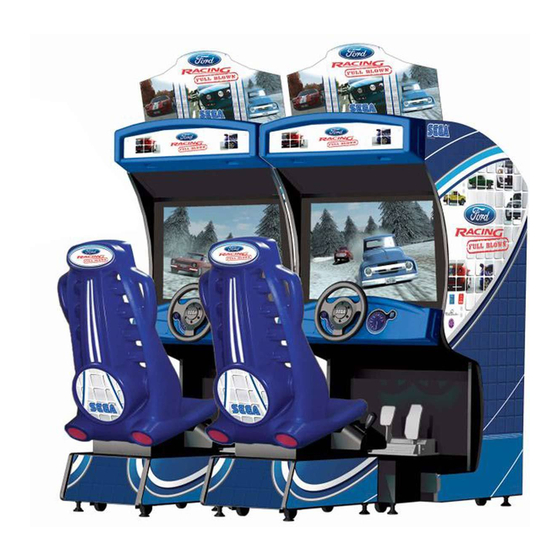
- Page 1 420-FRSM-02UK REV 2 TWIN DRIVING CABINET SERVICE MANUAL • Before using this product, read this MANUAL carefully to understand the contents stated herein. • After reading this MANUAL, be sure to keep it available nearby the product or somewhere convenient in order to be able to refer to it whenever necessary. Manufactured in the UK by Amusements Europe Limited...
- Page 2 Terms such as WARNING!, CAUTION, and IMPORTANT! Are used where an explanation is given which requires special attention, depending on the potential risk. SEGA is not responsible for injury or damage caused by use in a manner contrary to the instructions stated in this document. In order to prevent accidents warning stickers and printed instructions are applied in the places where a potentially hazardous situation relating to the product could arise.
- Page 3 SEGA. INSPECTION IMMEDIATELY AFTER TRANSPORTING THE PRODUCT TO LOCATION Normally, at the time of shipment, SEGA products are in a state which allow for immediate usage after transportation to location. Nevertheless, an irregular situation may occur during transportation. Before applying power to the product, check the following points to ensure that the procuct has been transported in a satisfactory status.
-
Page 4: Table Of Contents
CONTENTS SPECIFICATIONS ............................1 INTRODUCTION TO THIS MANUAL ......................1 HANDLING PRECAUTIONS .........................3 PRECAUTIONS REGARDING LOCATION AND INSTALLATION ............5 OPERATION............................7 NAME OF PARTS..........................9 ACCESSORIES ...........................10 FUSES ..............................11 ASSEMBLING WITH PRECAUTIONS ....................12 PRECAUTIONS TO BE TAKEN WHEN MOVING THE MACHINE ............23 BASIC CONTENTS OF THE GAME ....................24 EXPLANATION OF TEST AND DATA DISPLAY................25 10.1. - Page 5 25.4. ASSY HANDLE MECHA – FR-2500UK ..................89 25.5. ASSY SW PLATE – FR-2100UK....................90 25.6. ASSY HEADER – FR-0200UK .....................91 25.7. ASSY POP – FR-0270UK ......................91 25.8. ASSY FAN UNIT DC – HDT-1530UK ..................92 25.9. ASSY SEAT TWIN 1P – FR-5000UK...................93 25.10.
-
Page 6: Specifications
Only operate the product after carefully reading and sufficiently understanding the instructions. If the product fails to function satisfactory, non-technical personnel should under no circumstances touch the internal workings of this machine. Please contact where the product was purchased. SEGA AMUSEMENTS EUROPE LIMITED Suite 3a, Oaks house. 12-22 West Street, Epsom. - Page 7 DEFINITION OF THE QUALIFIED SERVICE ENGINEER AND MAINTENANCE PERSONEL Non-technical personnel who do not have technical knowledge and expertise should refrain from performing such work that this manual requires. Only QUALIFIED SERVICE ENGINEERS should carry out work either inside or outside the compass of this manual. Failure to comply with this instruction may cause a severe accident or even death.
-
Page 8: Handling Precautions
To avoid causing a fire hazard or an electric shock, do not make any unspecified changes to the product by replacing or changing parts or components without the express consent of SEGA. • Be sure to make periodic maintenance checks as stated herein. - Page 9 CONCERNING THE STICKER DISPLAY CONCERNING WARNING STICKERS SEGA product has stickers describing the product SEGA product has warning displays on stickers, manufacture number (Serial Number) and electrical labels or printed instructions adhered/attached to specification. If you require service assistance you or incorporated in the places where hazardous will require the Serial Number.
-
Page 10: Precautions Regarding Location And Installation
PRECAUTIONS REGARDING LOCATION AND INSTALLATION This product is an indoor amusement machine. Do not install it outside. Even indoors, avoid installing in places mentioned below sp as not to cause a fire, electric shock, injury and or malfunction. • Places subject to rain or water leakage, or places subject to high humidity in the proximity of an indoor swimming pool and or shower, bath etc. - Page 11 • Note that for transporting the machine to location the minimum necessary dimensions required for opening (of doors, etc.) are 1.85M x 1.05M (without shipping pallet.). • For the operation of this machine, secure a minimum area of 2.5M x 2.5M. For ventilation, provide an approximately 20cm space between the rear part of the cabinet and the wall.
-
Page 12: Operation
OPERATION PRECAUTIONS TO BE HEEDED BEFORE STARTING OPERATION To avoid injury be sure to constantly give careful attention to the behaviour and manner of players and spectators. In order to avoid accidents, check the following before starting operation. • Check if all of the adjusters are in contact with the surface. If they are not, the cabinet may move and cause an accident. - Page 13 PAYING ATTENTION TO CUSTOMERS To avoid injury or confrontation between customers, be sure to constantly give careful attention to the behaviour and manners of the players and visitors. • To avoid electric shock and or short circuit, do not allow customers to put hands or fingers or any other extraneous matter into the openings of the product.
-
Page 14: Name Of Parts
NAME OF PARTS Width Depth Height Weight Cockpit (per seat) 852mm 1630mm 1790mm Coin Chute Tower 220mm 300mm 550mm 15kg Pop Panel 800mm 430mm When Assembled 1713mm 1624mm 2200mm... -
Page 15: Accessories
ACCESSORIES When transporting the machine to location, make sure that the following parts are supplied. KEYS MASTER 9117 KEY TO DIFFER SERVICE MANUAL FR For opening and closing service For opening and closing secure This Manual doors door PT No 220-5575UK PT No 220-5574-110UK PT No: 420-FRSM-02UK SERVICE MANUAL SANWA... -
Page 16: Fuses
FUSES • Never touch places other than those specified. Touching places other than those specified can cause electric shock or short circuit. Disconnect the machine from the supply before attempting the replacement of any fuse. • Only QUALIFIED PERSONNEL should replace fuses. •... -
Page 17: Assembling With Precautions
ASSEMBLING WITH PRECAUTIONS • Perform assembly work by following the procedure herein stated. Failing to comply with the instructions can cause electric shock. • Assembling should be performed as stated in this manual. Since this is a complex machine, erroneous assembling can cause electric shock, machine damage and or impair functionality. - Page 18 • Only tighten fixings when all fixing are in place. If the fixings are tightened as the work progresses, it might not be possible to align the final fixings. ASSEMBLING 1 AND 2 PLAYER COCKPITS Step 1. Place the two cockpits side by side so that the artwork is facing outwards on both units.
- Page 19 Step 3. Making sure that there are no trapped wires, make the 4 (four) connections between both Master and Slave cabinets. Step 4. Make the remaining 4 (four) connections between the Coin Tower and Master and Slave units. Connect the 2 Earth ring terminals to the M4 stud on the floor of the Coin Tower and secure.
- Page 20 Step 5. Fix the coin tower to both cabinets by applying 8x M8x30 Hex Bolts (supplied) to the integral part of the tower. Step 6. Fit and secure the remaining 2x M8x30 Hex Bolts into the Coin Tower from inside both machines as show.
- Page 21 Step 7. Apply the 2x Join Brackets (FR-0013UK) to the outside of the cabinets as shown. Secure using the 8x M8x30 bolts (supplied). Step 8. The seat brackets are attached to the seat cabinet but will be inverted for transportation. Reposition the brackets so that they depict the figure to the right and secure with...
- Page 22 Step 9. Offer the seat cabinet up to the display cabinet. Before attaching both cabinets, make sure that the seat harness has been connected to the main harness. Once connection has been established, secure both seat cabinets to the main cabinets using 4x M8x30 Hex Bolts Black.
- Page 23 SECURING THE MACHINE INTO LOCATION • Make sure that all of the adjusters are in contact with the floor. If they are not, the cabinet may move and cause an accident or injury. • Be sure to use two people to perform this work. Depending on the specific work, there are some cases in which working by one person alone may cause an accident or injury.
- Page 24 INSTALLING THE POP PANEL. • To perform work safely and securely, be sure to use a step which is in a secure and stable condition. Performing work without a step or a step which is not in a suitable condition may cause and accident or injury. Step 1.
- Page 25 Step 2...
- Page 26 INSTALLING THE POWER CABLES • Be sure to use an independent power supply socket equipped with an Earth Leakage Breaker. Using a power supply without an Earth Leakage Breaker can lead to a fire or potential shock hazard. • THIS PRODUCT MUST BE EARTHED. •...
- Page 27 ASSEMBLY CHECK In the TEST MODE, ensure that the assembly has been made correctly and the IC BD is satisfactory. In the TEST MODE, perform the following tests. Select the INPUT TEST from the SYSTEM MENU (left screen). This screen enables the user to test individual input to the game.
-
Page 28: Precautions To Be Taken When Moving The Machine
PRECAUTIONS TO BE TAKEN WHEN MOVING THE MACHINE • When moving the machine, be sure to unplug the power cord from both the wall and machine ends. Moving the machine whilst either plug is inserted can cause either and accident or injury by electric shock. •... -
Page 29: Basic Contents Of The Game
BASIC CONTENTS OF THE GAME The following outlines basic routines to check whether the product is functioning satisfactory. If there is a deviation between what is explained in this section and the actual results of the machine then immediately look into the cause of fault and eliminate the cause to ensure satisfactory operation. -
Page 30: Explanation Of Test And Data Display
EXPLANATION OF TEST AND DATA DISPLAY By operating the buttons located on the VTS BD will enable the SYSTEM and GAME TEST MODES. When installing the machines, collecting cash or when the machine does not perform correctly, initiate a test sequence as explained in this section of the manual. The following outlines each test mode and explains in detail the movement throughout the menus. -
Page 31: Vts Board - Switches And Coin Counter
10.1. VTS BOARD – SWITCHES AND COIN COUNTER • Never touch places other than those specified. Touching parts in places not specified may cause electric shock or a short circuit hazard. • Adjust to the optimum sound volume taking in consideration the environmental requirements of the installation location. -
Page 32: Test Mode
10.2. TEST MODE • When changes are made in the TEST MODES, be sure to EXIT from the TEST MODES to return to GAME MODE. If power is turned OFF in TEST MODE, the new setting will not take effect. The Test Menu allows the functioning of each part of the cabinet to be checked, the monitor to be adjusted and the coins and various related game setting to be changed. -
Page 33: System Information
10.3. SYSTEM INFORMATION This test displays general system information regarding the hardware configuration and installed software. SYSTEM ID A unique 64 bit ID code to identify the system DISK IMAGE Version number for master disk image LAUNCHER VERSION Version number for System Launcher GAME SHELL VERSION Version number for Game Shell GAME NAME... -
Page 34: Ugci Test
10.4. UGCI TEST This test is used to test the network link between the computer and the UGCI board. COIN 1 COUNT Value of UGCI NVR coin count 1 COIN 2 COUNT Value of UGCI NVR coin count 2 VERSION Version number of UGCI board UGCI STATUS OK is the system can communicate with the UGCI board, otherwise a NOT... -
Page 35: Input Test
10.5. INPUT TEST This test is used to test and calibrate the peripherals connected to the UGCI interface. STEERING 00H = Full Left lock, 80H = Centre, FFH = Full right lock ACCELERATOR 00H = pedal fully up, FFH = pedal fully down BRAKE 00H = pedal fully up, FFH = pedal fully down GEAR SHIFT... -
Page 36: Calibration Test
10.6. CALIBRATION TEST This test is used to calibrate the analogue system input devices, i.e. the steering wheel, throttle pedal and brake pedal. STEERING LEFT VAL The current maximum left position of the steering wheel STEERING LEFT VAL The current maximum right position of the steering wheel BRAKE DOWN VAL The current maximum down position of the brake pedal BRAKE UP VAL... -
Page 37: Output Test
10.7. OUTPUT TEST This test is used to test any output signals (i.e. lamps) from the system. EXIT Exit to System Menu There are currently no output tests defined. Use the TEST button to return to the System Menu. -
Page 38: Coin Test
10.8. COIN TEST This test is used to set coin related parameters.: COIN CHUTE This option is fixed to COMMON COIN/CREDIT This is used to select how many credits per play are required. There are currently two options : 1 indicates 1 credit per play, and FREEPLAY indicates that no credits are required for play. -
Page 39: Sound Test
10.9. SOUND TEST This test is used to test the audio system is working correctly : OUTPUT TYPE This option is fixed to STEREO RIGHT SPEAKER When ON, a sound will be played from the RIGHT speaker LEFT SPEAKER When ON, a sound will be played from the LEFT speaker EXIT Exit to System Menu The user can select the LEFT and RIGHT speaker status to ON or OFF to test that speaker channel. -
Page 40: Crt Test
10.10. CRT TEST This test is used to test the game display is working correctly. It consists of two screens : COLOUR TEST GRID TEST Press the TEST button to move from COLOUR TEST to GRID TEST. Press the TEST button again to return to the System Menu. -
Page 41: Drive Board Test
10.11. DRIVE BOARD TEST This test is used to test the steering force feedback mechanism. STOP MOTOR Turn off all drive signals to the force feedback motor FULL LEFT Apply a maximum left signal to the force feedback motor (subject to power setting) FULL RIGHT Apply a maximum right signal to the force feedback motor (subject to power setting) MOTOR POWER... -
Page 42: Bookkeeping
10.12. BOOKKEEPING This test is used to review statistical data from the system. It consists of 3 main screens of data. Screen 1 contains an overview of game play data. 1PLYR GAMES PLAYED The total number of 1 player games played MPLYR GAMES PLAYED The total number of multi player games played COIN CREDITS... - Page 43 Bookkeeping Screen 2 contains a breakdown of game plays on a day to day basis. SUNDAY The total number of games played on a Sunday MONDAY The total number of games played on a Monday TUESDAY The total number of games played on a Tuesday WEDNESDAY The total number of games played on a Wednesday THURSDAY...
- Page 44 Bookkeeping Screen 3 contains a breakdown of game plays on a day to day basis. 00 - 01 The total number of games played between midnight and 1am 01 - 02 The total number of games played between 1am and 2am 23 - 00 The total number of games played between 11pm and midnight EXIT...
-
Page 45: Clock Settings
10.13. CLOCK SETTINGS This test is used to set the current time and date of the computer system. • Date cannot be changed until the AUTO UPDATE has been released. Once the AUTO UPDATE has been release and installed only then can the date be change. YEAR Variable from 2000 to 2050 MONTH... -
Page 46: Network Test
10.14. NETWORK TEST This test is used to test the network link between two computers in a twin cabinet. STATUS OK if Ethernet link is operating, NOT AVAILABLE otherwise CABINET ID ID of this cabinet, variable from 1 to 6. No linked cabinets should have the same ID. -
Page 47: Game Test Mode
10.15. GAME TEST MODE • All default setting shown in BOLD. • When setting the DIFFICULTY level, ALL cabinet MUST be set to the same setting. IF the DIFFICULTY settings differ from cabinet to cabinet then the value set on the PLAYER 1 cabinet will be used for all linked cabinets. -
Page 48: How To Play
HOW TO PLAY BASIC CONTROLS Insert coin and press credit transfer button to move credit to desired seat position. Press Start button to begin a game. Choose your car category, car, transmission and track. View choices with the steering wheel and enter your selection with the gas pedal. - Page 49 • Menu screen offers single or multiplayer game options Player uses steering wheel to move the selection to single player Player presses the gas pedal to select single player • The next option is to choose the vehicle class. Player uses the steering wheel to move to the selection required Player then presses the gas pedal to select to option.
- Page 50 • Menu screen offers 6 cars in three difficulty levels (Beginner, Intermediate & Advanced) Player uses steering wheel to move the selection to desired choice Player presses the gas pedal to select their chosen car • Menu screen offers Automatic or Manual transmission Player uses steering wheel to move the selection to desired choice Player presses the gas pedal to select their chosen transmission...
- Page 51 • Menu screen offers a selection of 6 tracks Player uses steering wheel to move the selection to desired choice Player presses the gas pedal to select their chosen category Race begins The screen below shows a screenshot of a race in progress.
- Page 52 On screen displays are highlighted and labelled in the image blow. During the race the player can select from three different viewpoint by pressing the view button. These view points are: In Car, behind close and behind far. The rear view mirror is only available to the player in the “In Car”...
- Page 53 GAME FLOW FOR MULTIPLAYER MODE Game flow: • Players inserts coin • Credit button flashes to indicate that credit is available • Players press the Credit button to transfer credit to their cabinet • “Press Start” flashes on screen to notify the players •...
- Page 54 Players wait for other players to join the game • Menu screen offers car categories of classic, modern, performance and off-road Players use steering wheel to move the selection to desired choice Players press the gas pedal to select their chosen category If players select different categories then a voting system is employed so that the category chosen by the greatest number of players is used...
- Page 55 • Menu screen offers 6 cars in three difficulty levels (Beginner, Intermediate & Advanced) Player uses steering wheel to move the selection to desired choice Player presses the gas pedal to select their chosen car • Menu screen offers Automatic or Manual transmission Player use steering wheel to move the selection to desired choice Players press the gas pedal to select their chosen transmission...
- Page 56 • Menu screen offers a selection of 6 tracks Players use steering wheel to move the selection to desired choice Players press the gas pedal to select their chosen category If players select different tracks then a voting system is employed so that the category chosen by the greatest number of players is used •...
- Page 57 TECHNIQUES AND SECRETS Super Start If a player keeps the Revs of their car between 5,000 and 6,000 when the race begins they are given a speed boost. Hidden Shortcuts Some of the tracks have hidden shortcuts that can help reduce lap times. CARS The table below details all the cars available.
- Page 58 The tables below detail the tracks available to select initially and after the preset update day. Initial Tracks Road Tracks Off Road Tracks Harbour – Forward White Sands - Reverse Railroad – Reverse Voodoo Village - Forward Quaker Town – Forward Colonial Grounds - Reverse Mountain Village - Forward Fishing Town - Forward...
-
Page 59: Upgrades
UPGRADES UPGRADES This product comes with an AUTOMATIC upgrade in software. On the 1 November 2006 the machine will perform an AUTOMATIC UPGRADE and the software will be updated to give the player a number of NEW racing track and NEW cars. 28 days prior the OFFICIAL software drop, players will be advised that an UPGRADE will take place. -
Page 60: Handle Mechanism
HANDLE MECHANISM • Be sure to turn power off before performing work. • Immediately after the game has finished, the motor may still be very hot after operation. When performing any work when handling the motor is necessary, wait until the motor has cooled. •... -
Page 61: Replacing And Adjusting The Handle's V.r
13.2. REPLACING AND ADJUSTING THE HANDLE’S V.R. • Never touch places or parts other than those specified. Touching places not specified may cause electric shock or a short circuit hazard. • After the replacement or adjustment of the steering V.R., be sure to set the centering value of the V.R in test mode. -
Page 62: Greasing
13.3. GREASING • Be sure to use suitable grease for the purpose. Using a non-suitable product may cause damage to parts. Apply the grease to the V.R gear once every 3 months for optimum performance. GREASE AT THIS POINT EVERY 3 MONTHS... -
Page 63: Shift Lever
SHIFT LEVER • Before starting work, ensure that the Power is disconnected and the machine is switch off. Failure to observe this precaution may cause injury or electric shock. • Use care so as not to damage wiring. Damaged wires can cause electric shock or a short circuit hazard. -
Page 64: Switch Replacement
14.2. SWITCH REPLACEMENT Each Microswitch is secured using 2 machine screws. Remove the 2 screws and replace the Microswitch using the illustration below. 1. Disconnect the wiring connectors of the switch which is to be replaced. 2. Remove the 2 self tap screws to remove the Microswitch. GREASING Apply grease once every 3 months to the specified areas to ensure smooth operation throughout the product life. -
Page 65: Accelerator & Brake
ACCELERATOR & BRAKE • Before starting work, ensure that the Power is disconnected and the machine is switch off. Failure to observe this precaution may cause injury or electric shock. • Use care so as not to damage wiring. Damaged wires can cause electric shock or a short circuit hazard. - Page 66 REPLACING THE POTENTIOMETER 1. Turn the power off. 2. Take out the 2 screws and remove the top cover. 3. Disconnect the connector of the volume pot to be replaced. 4. Remove the screws which secure the Potentiocover. 5. Remove the Potentiobase together with the Potentiometer. 6.
-
Page 67: Coin Selector
COIN SELECTOR HANDLING COIN JAMS If the coin is not rejected when the REJECT button on the COIN CHUTE DOOR is pressed, open the COIN CHUTE DOOR and open the selector gate. After removing the jammed coin, put a normal coin in through the COIN ACCEPTOR and check to see that the selector correctly functions. CLEANING A MECHANICAL COIN SELECTOR •... -
Page 68: Monitor
• Using the monitor by converting it without obtaining prior permission is not allowed. SEGA shall not be liable for any malfunctioning or accident caused by unauthorised work being carried out. • Primary side and Secondary side. The monitor’s circuit which is divided into the Primary side and Secondary side are electrically isolated. -
Page 69: Cautions To Be Aware Of When Cleaning The Crt Surfaces
• Static electricity. Touching the CRT surface can sometimes cause static electricity. This is because the CRT surface is subject to static and will not adversely affect the human body. • Installation and removal.. Ensure that the Degause Coil, Fly Back Transformer, Anode Lead and Focus leads are not positioned close to sheet metalwork sharp edges. -
Page 70: Adjusting The Picture
17.3. ADJUSTING THE PICTURE • Monitor adjustments have been made at the time of shipment. Therefore, do not make further adjustments without a justifiable reason. Adjusting the monitor which contains high tension parts is a dangerous task. Also, an erroneous adjustment can cause deviated synchronization and image fault, resulting in malfunction. -
Page 71: Replacement Of Fluorescent Lamps
REPLACEMENT OF FLUORESCENT LAMPS • When performing any work, be sure to turn power off. Working with power on can cause electric shock and short circuit. • The Fluorescent lamp can get hot towards the ends of the unit. Be careful when •... - Page 72 Once removed, replace the lamp with new and reassemble in reverse.
-
Page 73: Replacement Of Button Lamps
REPLACEMENT OF BUTTON LAMPS • Before starting work, ensure that the Power is disconnected and the machine is switch off. Failure to observe this precaution may cause injury or electric shock. • Use care so as not to damage wiring. Damaged wires can cause electric shock or a short circuit hazard. - Page 74 Replace the bulb or LED with the correct type and reverse process to re-assemble.
-
Page 75: Game Board
The electronic parts contained within the GAME BD CASE can be damaged due to human body static electricity. Before performing and component level work, be sure to gain acknowledgement from SEGA. • Before attempting component level work be sure to discharge physically accumulated static by touching grounded metallic surfaces. - Page 76 3. Remove the rear door and set safely to one side. 4. Disconnect all harnesses from the Game Board. 5. Remove the Security Device. 6. Loosen the four (4) self tapping screws. 7. Slide the Game Board to the right and remove. 8.
-
Page 77: Game Board Connections
20.2. GAME BOARD CONNECTIONS • When the security device is installed, the Game Board becomes proprietary to this product. • For safety reasons the GAME BOARD is fitted with a 10 second power on delay. If power is turned OFF and ON again within the 10 seconds delay period, the GAME BOARD will NOT power up. -
Page 78: Ugci Board
If the UGCI BD or the USB connection to the UGCI BD fail during game the game will end and the SEGA logo will appear on screen with the error “I/O FAULT”. If this occurs, switch off the machine and replace the faulty item. -
Page 79: Network Play
NETWORK PLAY Up to 3 twins (6 seats) can be linked for network play. Properly connected network cables and correct network play settings are required for network play. • Before starting to work, ensure that the Power SW is OFF. Failure to observe this can cause electric shock or short circuit. - Page 80 SPACING OF THE GAME MACHINES Diagram to link 3 twins for network play Diagram to link 2 twins for network play...
-
Page 81: Connections For Network Play
22.1. CONNECTIONS FOR NETWORK PLAY To enable network play, the hubs inside each of the master game machines must be connected with network (LAN) cables. Connect the hub inside the master machine to each of the hubs inside the other machines. -
Page 82: Network Play Settings
22.2. NETWORK PLAY SETTINGS Each for the linked machines must be set up for network play. If the machines are not set up correctly, network play will not be possible. HOW TO SET UP THE MACHINE FOR NETWORK PLAY 1. Turn the power off on each machine to be used for network play. 2. -
Page 83: Coin Settings
COIN SETTINGS Game credits between the Coin Mechanism and the game board for this machine are controlled by a VTS board. This electronic circuit allows the price of play to be set for a range of different countries. These functions are set on Dual In Line (DIL) PCB mounted switches. DIL-3 is used to set the currency (or coin ratio) and DIL-1 the price of play. - Page 84 • The 3 Service Button on the VTS BD, if pressed will trigger a COIN CREDIT that will be recorded within the BOOKKEEPPING but not on the Mechanical Coin Counter. Illustration shows VTS PCB. • The CREDIT SETTINGS as displayed in the COIN TEST of the SYSTEM TEST MENU should always be set to 1 COIN = 1 CREDIT when using the VTS PCB.
-
Page 85: Vts Credit Board Option Settings
23.1. VTS CREDIT BOARD OPTION SETTINGS Credit Board Mode Settings Switch 3 Country Setting Switch 3 Setting Coin Validator Programming C120/SR3 Only SW1 SW2 SW3 SW4 SW5 SW6 COIN1 COIN2 COIN3 COIN4 COIN5 COIN6 COIN7 COIN8 COIN9 COIN10 COIN11 COIN12 Coin Controls £1 50p new... -
Page 86: Price Of Play Settings Uk
23.2. PRICE OF PLAY SETTINGS UK Price Bonus DIL Switch 1 50p = 5 plays £1 = 10 plays £2 = 20 plays 50p = 6 plays @ 8.33p per play £1 = 12 plays @ 8.33p per play £2 = 24 plays @ 8.33p per play 50p = 2.5 plays £1= 5 plays £2 = 10 plays... -
Page 87: Price Of Play Settings Euro
23.3. PRICE OF PLAY SETTINGS EURO Price Bonus DIL Switch 1 10¢ 50¢ = 5 plays €1 = 10 plays €2 = 20 plays 10¢ 50¢ = 6 plays @ 8.33p per play €1 = 12 plays @ 8.33¢ per play €2 = 24 plays @ 8.33¢... -
Page 88: Designed Related Parts
DESIGNED RELATED PARTS... -
Page 89: Parts List
PARTS LIST... -
Page 90: Top Assy Ford Racing Twin - Fr00001Uk
25.1. TOP ASSY FORD RACING TWIN – FR00001UK PT NUMBER DESCRIPTION FR-10001UK ASSY MAIN 1P FR-5000UK ASSY SEAT TWIN 1P FR-0400UK ASSY AC BRKT MAIN FR-0700UK ASSY AC BRKT SUB FR-1100UK ASSY PEDAL BASE L FR-1150UK ASSY PEDAL BASE R FR-0300UK ASSY COINCHUTE TOWER FR-0021UK... -
Page 91: Assy Main 1P - Fr-10001Uk
25.2. ASSY MAIN 1P – FR-10001UK Continues overleaf... - Page 92 PT NUMBER DESCRIPTION FR-1120UKI FR MAIN CABI FR-2000UK ASSY CONTROL PANEL FR-0200UK ASSY HEADER FR-0270UK ASSY POP FR-1022UK MONITOR SUPPORT FR-1023UK MASK FR-1025UK SPEAKER PNL FR-1026UK BKT SUPPORT CNTRL PNL LWR FR-1027UK BRKT SUPP HEADER COVER FR-1028UK PLATE BACK HEADER COVER FR-1132UK PLATE UP LIGHT HDF-1081UK...
-
Page 93: Assy Control Panel - Fr-2000Uk
25.3. ASSY CONTROL PANEL – FR-2000UK PT NUMBER DESCRIPTION FR-2001UK CONTROL PANEL COVER FR-2002UK CONTROL PANEL BRKT TWIN FR-2003UK HANDLE COLLAR FR-2100UK ASSY SW PLATE FR-2004UK FORMING CNTRL PAN CLOSURE FR-2006UK BRKT FRONT CNTRL PNL FR-2010UK STICKER CONSOLE 422-FRIPI-UK PLAY INSTRUCTION FR TWIN FR-2012UK DIALS CNTRL PAN L FR-2013UK... -
Page 94: Assy Handle Mecha - Fr-2500Uk
25.4. ASSY HANDLE MECHA – FR-2500UK... -
Page 95: Assy Sw Plate - Fr-2100Uk
25.5. ASSY SW PLATE – FR-2100UK PT NUMBER DESCRIPTION FR-2101UK BUTTON PLATE FR-2102UK STICKER BUTTON PLATE 509-6001-Y BTN RND 12V YELLOW 22-2060-4LP 509-6001-B BTN RND 12V BLUE 22-2060-6BBLP 509-6001-G BTN RND 12V GRN 22-2060-5LP LT1051 LED CLUSTER YEL 161-12103-4 LT1052 LED CLUSTER GRN 161-12103-5 LT1053 LED CLUSTER BLU 161-12103-X... -
Page 96: Assy Header - Fr-0200Uk
25.6. ASSY HEADER – FR-0200UK PT NUMBER DESCRIPTION FR-0201UK HEADER COVER FR-0202UK HEADER SUPPORT BRKT FR-0203UK HEADER 25.7. ASSY POP – FR-0270UK PT NUMBER DESCRIPTION FR-2071UK POP PANEL FR FR-0272UK BRKT SUPP POP LOWER FR-0273UK BRKT SUPP STRUT L FR-0274UK BRKT SUPP STRUT R FR-0275UK BRKT CROSS BRACE POP... -
Page 97: Assy Fan Unit Dc - Hdt-1530Uk
25.8. ASSY FAN UNIT DC – HDT-1530UK PT NUMBER DESCRIPTION 105-5340-01 FAN BKT LONG EC814500 12V DC FAN 120MM KD1212PMS3-6A FN1012 FAN GUARD METAL 120MM FG-12 HDF-60004UK WIRE HARNESS FAN LINK (NOT SHOWN) -
Page 98: Assy Seat Twin 1P - Fr-5000Uk
25.9. ASSY SEAT TWIN 1P – FR-5000UK PT NUMBER DESCRIPTION FR-5500UK ASSY SEAT CABI FR-5600UK ASSY SEAT UNIT 25.10. ASSY SEAT CABI – FR-5500UK PT NUMBER DESCRIPTION FR-5501UK WOODEN SEAT CABI MA1019 CASTER 75 FR-5505UK JOINT PLATE 601-5699UK LEG ADJUSTER M16X100 1L/NUT... -
Page 99: Assy Seat Unit - Fr-5600Uk
25.11. ASSY SEAT UNIT – FR-5600UK PT NUMBER DESCRIPTION FR-5601UK SEAT BASE FR-5602UK SHIFT ENCLOSURE FR-5604UK SEAT ADAPTOR PLATE 610-0408-91 UP/DOWN SHIFTER AL RND-0039 PLATE U/D SHIFT MTNG RND-0063-01 SEAT MIDWAY 04-12452 RAL5005 601-9059-91 SEAT RAIL L 601-9060-91 SEAT RAIL R... -
Page 100: Assy Ac Brkt Main - Fr-0400Uk
25.12. ASSY AC BRKT MAIN – FR-0400UK PT NUMBER DESCRIPTION HDF-0661UK BRKT AC HDF EP1382 FILTER SCHAFFNER FN682-10/06 EP1387 IEC INLET & SW BZV01/Z0000/70 LB1096 STICKER PROTECTIVE EARTH FR-60011UK WIRE HARNESS AC BRKT FR (NOT SHOWN) 514-5078-10000 FUSE 5X20 CERAMIC SB 10A 25.13. -
Page 101: Assy Pedal Base L - Fr-1100Uk
25.14. ASSY PEDAL BASE L – FR-1100UK PT NUMBER DESCRIPTION FR-1101UK BASE PLATE L SPG-2200 ASSY ACCEL & BRAKE FR-2222UK ANTI FINGER TRAP PLATE L FR-2223UK ANTI FINGER TRAP PLATE R FRI-2201 FOOT REST FRI 25.15. ASSY PEDAL BASE R – FR-1150UK PT NUMBER DESCRIPTION FR-1151UK... -
Page 102: Assy Brake & Accel - Spg-2200
25.16. ASSY BRAKE & ACCEL – SPG-2200... -
Page 104: Assy Main Bd Pc Master - Fr-4500Uk
25.17. ASSY MAIN BD PC MASTER – FR-4500UK PT NUMBER DESCRIPTION FR-4501UK MAIN BD PC BASE 610-0001-01UK ASSY CASE PC LB1101 STICKER WARNING BATTERY LB1111 STICKER PLEASE RECYCLE 400-0012-0100UK POWER SUPPLY 12V 100W 400-0024-0100UK POWER SUPPLY 24V 100W 838-CA-150 AUDIO AMP 15W FR-838-001UK MOTOR CONT ISO HAPP 50-2000-03 FR-838-002UK... -
Page 105: Assy Main Bd Pc Slave - Fr-4600Uk
25.18. ASSY MAIN BD PC SLAVE – FR-4600UK PT NUMBER DESCRIPTION FR-4501UK MAIN BD PC BASE 610-0001-01UK ASSY CASE PC LB1101 STICKER WARNING BATTERY LB1111 STICKER PLEASE RECYCLE 838-CA-150 AUDIO AMP 15W FR-838-001UK MOTOR CONT ISO HAPP 50-2000-03 FR-838-002UK UGCI DRIVING HAPP 95-0800-10 FR-4550-01UK ASSY iBUTTON PROGRAMMED EUR... -
Page 106: Assy Coinchute Tower
25.19. ASSY COINCHUTE TOWER PT NUMBER DESCRIPTION FR-0301UK COIN CHUTE TOWER FR VTS-FRI-T VTS BOARD FRI TWIN DUT-0302UK COIN PATH PLATE PP1087 CASHBOX FOR MINI DOOR FR-0303UK CCT FLOOR 220-5374-01 DOOR DFMD C120 UNIVERSAL 220-5725-05B DOOR SINGLE MINI SECURITY BLK 220-5574-110UK LOCK KEY DIFFERS 11MM (NOT SHOWN) -
Page 107: Assy Installation Kit Fr Twin - Fr-Inst-Tw
25.20. ASSY INSTALLATION KIT FR TWIN – FR-INST-TW PT NUMBER DESCRIPTION FR-0300UK ASSY COINCHUTE TOWER FR-0013UK JOINT BRKT REAR PK0388 INST KIT BOX FR TWIN 440-CS0186UK STICKER C EPILEPSY MULTI 600-7269-0500UK ASSY LAN CABLE 0500CM 420-5827-91UK SERVICE MANUAL SANWA 31K 420-FRSM-02UK SERVICE MANUAL FR TWIN OS1019... -
Page 108: Appendix A - Electrical Schematic
APPENDIX A - ELECTRICAL SCHEMATIC 26.1. WIRE COLOURS THE WIRE COLOUR CODE IS AS FOLLOWS: PINK SKY BLUE BROWN PURPLE LIGHT GREEN Wires other than those of any of the colours listed above will be displayed by 2 alphanumeric characters: BLUE YELLOW GREEN... - Page 111 SEGA AMUSEMENT EUROPE encourages the recycling of its products is committed to transitioning its products to meet with WEEE and RoHS requirements.
Need help?
Do you have a question about the FORD RACING TWIN-FULL BLOWN and is the answer not in the manual?
Questions and answers