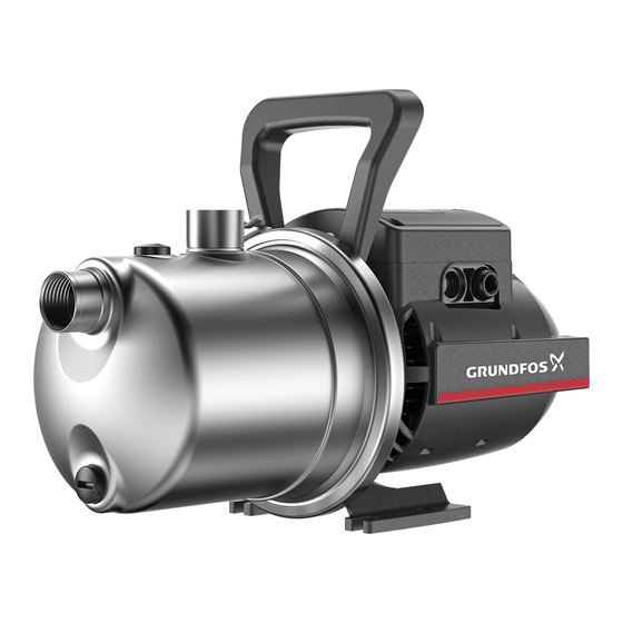
Grundfos JP Series Installation And Operation Instructions Manual
Hide thumbs
Also See for JP Series:
- Installation and operating instructions manual (12 pages) ,
- Installation and operating instructions manual (19 pages)
Table of Contents
Advertisement
Advertisement
Table of Contents

Summary of Contents for Grundfos JP Series
- Page 1 GRUNDFOS INSTRUCTIONS JP and JP Booster Installation and operating instructions...
-
Page 2: Table Of Contents
Hazard statements ......5 The symbols and hazard statements below may appear in Grundfos Notes ........5 installation and operating instructions, safety instructions and service instructions. -
Page 3: Scope Of Delivery, Jp Booster
2.3 Scope of delivery, JP Booster 3.2 Mechanical installation The box contains the following items: WARNING • 1 Grundfos JP Booster Electric shock Death or serious personal injury • 1 quick guide ‐ Switch off the power supply before you start any work •... - Page 4 Fig. Inlet pipe with gradual upward slope towards the pump 3.2.3.1 Maximum system pressure Make sure that the system in which the pump is installed is designed for the maximum pump pressure. The maximum inlet pressure depends on the head at the actual duty point.
-
Page 5: Electrical Connection
Fig. Correct pipe sizing for connection to the pump inlet or outlet 3.2.4 Installation examples We recommend that you follow the installation examples. Valves are not supplied with the pump. 3.2.4.1 Suction from a tank This installation example shows JP PM, but it applies to all variants of the JP range. - Page 6 3.3.3 Connecting products without a cable Make sure that the electrical installation supports the rated current [A] of the product. See the product's nameplate. WARNING Electric shock Death or serious personal injury 3.3.1 Connecting products with a plug ‐ Power supply cables without a plug must be connected to a supply disconnecting device incorporated in the WARNING fixed wiring according to the local wiring rules.
-
Page 7: Startup Of The Product
Strip the cable conductors and add cable shoes. Related information 3.3.2 Connecting products without a plug 3.3.4 Wiring diagram 3.3.4 Wiring diagram Pos. Description Blue Black Capacitor Related information 3.3.3 Connecting products without a cable 3.3.5 Motor protection The pump incorporates current- and temperature-dependent motor protection. -
Page 8: Priming The Product
JP Boosters are available in the following variants: • JP PM: a jet pump with a pressure manager (Grundfos PM 1) • JP PT-V: a jet pump with a vertical pressure tank and a pressure switch •... -
Page 9: Product Overview, Jp
5.1 Product overview, JP 5.3 Intended use Only use the product according to the specifications stated in these installation and operating instructions. The product is suitable for pressure boosting of clean water in domestic water-supply systems. Related information 4. Startup of the product 5.4 Pumped liquids 5.3.1 Intended use of the AISI 316 variant WARNING... -
Page 10: Identification
If water escapes during the precharge-pressure check, the Tank type, if applicable: membrane is defective. • V: Vertical 6.3 Service kits • H: Horizontal For further information on service kits, see Grundfos Product Center 1x230 V Voltage [V] at www.product-selection.grundfos.com. -
Page 11: Taking The Product Out Of Operation
7. Taking the product out of operation Drain the pump by removing the drain plug. Unscrew the hose on the tank. WARNING Electric shock Tilt the tank so that the water flows out. Death or serious personal injury When the tank is empty, refit the hose. ‐... -
Page 12: The Pump Does Not Start
Cause The suction lift is too high. WARNING Chemical hazard Remedy Change the position of the pump. The suction lift Death or serious personal injury must not exceed 8 m. ‐ Make sure that the product has only been used for water. -
Page 13: Fault Finding Boosters With A Pressure Tank
Repair or replace the pressure manager. function. Find more information in the service instructions Remedy Make sure that the water supply is sufficient. at https://product-selection.grundfos.com. 8.4.7 The pump does not stop Cause The power supply to the pump is disconnected. Cause... -
Page 14: Technical Data
This product or parts of it must be disposed of in an environmentally sound way. Use the public or private waste collection service. If this is not possible, contact the nearest Grundfos company or service workshop. Dispose of the waste battery through the national collective... - Page 15 Съдържание на доставяния комплект, JP Booster ..19 В инструкциите за монтаж и експлоатация, инструкциите за безопасност и сервизните инструкции на Grundfos може да се Инсталиране на продукта ....19 появяват...
- Page 16 JP 4-54 ИЗКЛЮЧЕНА: 40 мин ИЗКЛЮЧЕНА: 40 мин Кашонът съдържа следните артикули: ВКЛЮЧЕНА: 20 мин ВКЛЮЧЕНА: 30 мин • 1 помпа Grundfos JP JP 5-48 ИЗКЛЮЧЕНА: 40 мин ИЗКЛЮЧЕНА: 30 мин • 1 комплект дръжка за повдигане • 1 кратко ръководство...
- Page 17 Размери на тръбите: • Диаметърът на входната тръба трябва да е по- голям от 1", ако входната тръба е по-дълга от 10 m или смукателната височина надвишава 4 m. • Ако за входна тръба се използва маркуч, той трябва да не може да се прегъва. Препоръчваме...
- Page 18 Tel.: +387 33 592 480 Centre Turkey Fax: +387 33 590 465 29-33 Wing Hong Street & 68 King Lam GRUNDFOS Pumper A/S GRUNDFOS POMPA San. ve Tic. Ltd. Sti. www.ba.grundfos.com Street, Cheung Sha Wan Strømsveien 344 Gebze Organize Sanayi Bölgesi E-mail: grundfos@bih.net.ba...
- Page 19 99520338 122018 ECM: 1244124...


Need help?
Do you have a question about the JP Series and is the answer not in the manual?
Questions and answers