Table of Contents
Advertisement
Advertisement
Table of Contents

Related Manuals for EdilKamin NARA PLUS


Summary of Contents for EdilKamin NARA PLUS
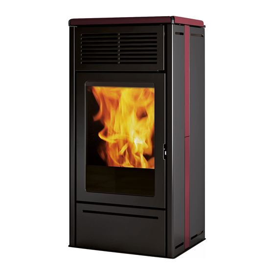
- Page 1 NARA PLUS PELLET STOVE Installation, use and maintenance...
-
Page 2: Table Of Contents
Instructions for use Maintenance Troubleshooting The original language of this manual is Italian EDILKAMIN S.p.A., with registered offices in Via Vincenzo Monti 47 - 20123 Milan - tax code and VAT number 00192220192 Declares, under its sole responsibility, that: The pellet stove mentioned below is conforming with EU... - Page 3 Proper commissioning is required for activation of the with local and national law and European regulations. For the Edilkamin warranty. The warranty is only valid in the country installation, and for anything not specifically indicated in the of sale of the product.
-
Page 4: Safety Information
CLIMB ONTO THE PRODUCT OR USE IT AS A the warranty certificate inside the product: neither SUPPORT. Risk of damage and injury. Edilkamin nor the reseller are liable for damage • use of the stove with the hearth open. DO NOT resulting from incorrect installation or maintenance. -
Page 5: Dimensions
DIMENSIONS DIMENSIONS (cm) Ø 4 cm Ø 4 cm aria combustion air combustione Ø 8 cm fumes outlet Ø 4 cm aria Ø 8 cm uscita fumi Ø 4 cm aria combustione combustione Ø 8 cm uscita fumi Ø 8 cm uscita fumi Ø... -
Page 6: Technical Characteristics
2,4 GHz Protection Fuse 4 AT, 250 Vac 5x20 The above data are illustrative and are drawn from the certification by a notified body. EDILKAMIN s.p.a. reserves the right to modify the product without notification in the interests of improvement. -
Page 7: Packaging
PACKAGING PREPARATION AND UNPACKING Contents of the bag of small parts The packaging materials are neither toxic nor noxious • n° 6 rods for the three ceramic top parts; and do not require special disposal. • n° 6 ceramic dampers for the top The user is responsible for storing, disposing or and •... - Page 8 INSTALLATION INSTALLING THE LINING Proceed as follows (refer to the figures): • Take the stove off the pallet by removing the screws. PLEASE NOTE: DO NOT ATTEMPT TO TAKE THE STOVE PALLET WITHOUT FIRST REMOVING THE SIDE PANELS AND THE SCREWS (TWO PER SIDE) ANCHORING THE STOVE TO THE PALLET The drawings are indicative and valid for mounting the...
- Page 9 INSTALLATION Fit the ceramic panels (two on each side) to the side panels with the bolts and washers included in the bag of small parts Do not force the screw into the threaded bushingit may break. washers bolts * On the lower right side, use the countersunk screw (M 4x8) provided to avoid interference with the internal parts...
- Page 10 INSTALLATION Fit the interlocking side panels and screw down the bolts on the back...
- Page 11 INSTALLATION Screw the rods into the top ceramics (2 rods for each ceramic part) Please apply high temperature silicone under the holes ( A) to strengthen the stability of the component Fit the dampers onto the top...
- Page 12 INSTALLATION Position the three ceramic parts on the top. use the shims to adjust the ceramics if they are slightly misaligned (this is perfectly normal)
- Page 13 • The appliance may not be installed in a bedroom, Contact the authorised Edilkamin Technical Assistance bathroom or in the same room as other equipment Centre. which draws air for combustion from the room itself, or in any area with an explosive atmosphere.
- Page 14 INSTALLATION FLUE SYSTEM • be certified, with a chimney plate if metal (Fumes duct, flue and chimney pot) • be of uniform cross section or vary in cross section Thsi chapter has been drawn up pursuant to European only immediately after the outlet, not at some mid regulations EN 13384, EN 1443, EN 1856 and EN point of its length 1457.
- Page 15 INSTALLATION THE FLUE: EXTERNAL AIR INTAKE Further to the general prescriptions for the fumes duct In general, we suggest two ways for ensuring a proper and flue, the flue: flow of combustion air. • must serve solely to exhaust fumes •...
- Page 16 The electrical system must be compliant; check the 2) Use the provided gloves when operation of the earth in particular. loading the stove while it is Edilkamin is not responsible for malfunctions resulting operating and hence hot to the from an improperly earthed system. touch.
-
Page 17: User Instructions
USER INSTRUCTIONS OPERATION PHASES Further to the above operational procedures, the stove Description. has the following phases The access to and adjustment of these functions is described on page: - Ignition (display reads ON ) Flame ignites and grows stable Method Settings This is the result of:... - Page 18 • hooked up electrically use. Edilkamin and the reseller will not consider • THE AUDIBLE SIGNALS PRESS THE claims for battery life under any circumstances. If...
- Page 19 USER INSTRUCTIONS The display reads the POSSIBLE STATES described below: - OFF STATE The product is “deactivated” and will not produce heat due to manual switching off using the ON/OFF button on the remote control or due to an external contact (crono, phone dialler) The display shows the current time, room temperature and the status in relation to which the product is OFF.
- Page 20 USER INSTRUCTIONS USER CONTROLS (REMOTE CONTROL) Ventilation - ON/OFF The product is equipped with two fans, defined in the - Switch-on/switch-off control logic as fan 1 and 2, and displayed as positions - Manual mode setting 1 and 2 (see below). •...
- Page 21 USER INSTRUCTIONS - Stand by - Relax function When the Stand by function is active, in automatic Natural convection function with automatic power and timer modes, the product shuts off when the limiting. temperature setpoint is reached and turns on again This function is available in all modes: automatic, when the temperature drops.
- Page 22 USER INSTRUCTIONS Crono The following screen will appear. Scroll to “ENABLE” When the Crono function is active, the user sets a (underlined) using the “+/-” buttons. temperature setpoint and a time zone for which that To enable the Crono function to 7 days a week or setpoint is specified.
- Page 23 USER INSTRUCTIONS To combine one of the three temperatures To set the temperature setpoints (“TEMP” on to a time period (“SET” on the display), from the the display), from the Crono function, press the “OK” Crono function, press the “OK” button. The following button.
- Page 24 USER INSTRUCTIONS The second screen (accessible by pressing the “OK” To view/change the settings (“CHANGE” on button from the first screen) allows you to set the start the display), from the Crono function, press the “OK” button. The following screen will appear. and end time of the time period matching the chosen Scroll to “CHANGE”...
- Page 25 USER INSTRUCTIONS Night (deferred switching on/off) Load Pellets This function switches the product on/off after a set Allows you to load pellets after the screw feeder has emptied following a no-pellets alarm. period from activation of the function. Useful for the technician during commissioning. This is convenient if you go to bed and want the product Available only in the OFF state.
-
Page 26: Technical Menu
USER INSTRUCTIONS Date/Time Beep Sets the current date/time. Allows you to enable/disable the beep. This displays the first time the remote control is To access the function from the main menu (as activated with the stove powered on, or by selecting indicated in the Menu section above), press the M the option in the menu. -
Page 27: Maintenance
MAINTENANCE Before doing any maintenance, disconnect the appliance from the mains. Regular maintenance essential keeping the appliance in good working order. FAILURE TO SERVICE THE STOVE WILL PREVENT IT FROM WORKING PROPERLY. Any problems due to failure to service the stove will void the warranty. - Page 28 MAINTENANCE WEEKLY MAINTENANCE Extract the ceiling panel (3 - fig. C) and drop the residues into the ash tray. The ceiling panel is subject to wear; the manufacturer is not responsible for breakage, especially if this occurs when its is being removed or repositioned. Once you have finished cleaning the stove, make sure the grate is PROPERLY SEATED (A - fig.
- Page 29 For any spare parts, contact your reseller or technician. months. Using non-original spare parts may damage the appliance and relieves Edilkamin of all liability for You should clean the chimney system at least once a damage resulting therefrom. year (check local regulations for details).
-
Page 30: Troubleshooting
TROUBLESHOOTING If problems occur, the stove shuts itself off automatically. The display will show the reason (see below). DO NOT disconnect the electrical power supply. To start the product up again, allow the shutdown procedure to complete, then press the remote control's ON/OFF button or the simplified ignition button. - Page 31 The battery symbol displays on the remote’s display if the battery is low. MAINTENANCE: A wrench symbol is shown on the display after 2000 hours of operation. The product is working, but it must be serviced by an authorised Edilkamin technician.
- Page 32 *941381-GB* w w w . e d i l k a m i n . c o m cod. 941381-GB 06.18/D...
Need help?
Do you have a question about the NARA PLUS and is the answer not in the manual?
Questions and answers