
Related Manuals for EdilKamin Blade2 12 Up


Summary of Contents for EdilKamin Blade2 12 Up
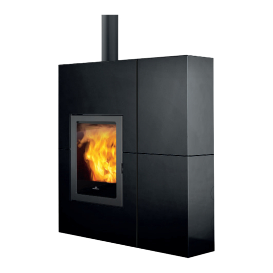
- Page 1 Blade2 12 Up PELLET STOVE For all updates visit www.edilkamin.com UK Installation, use and maintenance page...
- Page 2 The original language of this manual is Italian EDILKAMIN S.p.A., with registered offices in Via P . Moscati 8 - 20154 Milan - tax code and VAT number 00192220192 Declares, under its sole responsibility, that: The pellet stove mentioned below is conforming with EU...
-
Page 3: Meaning Of Symbols
Puissance a l'eau / Potenza resa all'acqua Space heating output / Leistung Raum 12,1 Model / Modell / Modele / Modello Environnement puissance / Potenza resa all'ambiente BLADE2 12 UP Efficiency / Wirkungsgrad / Rendement / Rendimento 90,6 93,9 Year of construction/Produktionsiahr 0.004... -
Page 4: Safety Information
CLIMB ONTO THE PRODUCT OR USE IT AS A the warranty certificate inside the product: neither SUPPORT. Risk of damage and injury. Edilkamin nor the reseller are liable for damage • use of the stove with the hearth open. DO NOT resulting from incorrect installation or maintenance. - Page 5 39,5 NOTE: • The names of Edilkamin offi cial, authorised technical assistance centres and distributors are available ONLY at www.edilkamin.com. • Ducting length and vent outlet temperature, depend on the conditions of use and installation. It is therefore suggested to size the ducting system.
- Page 6 39,5 NOTE: • The names of Edilkamin offi cial, authorised technical assistance centres (TAC) and distributors are available ONLY at www.edilkamin.com. • Ducting length and vent outlet temperature, depend on the conditions of use and installation. It is therefore suggested to size the ducting system.
-
Page 7: Technical Data
TECHNICAL DATA TECHNICAL CHARACTERISTICS in accordance with EN 13229 Best results are achieved with the clean glass system closed. Use the supplied gasket, by the installer. Nominal power Reduced power 12,1 Available power Efficiency 90,6 93,9 CO emissions at 13% O 0,004 0,015 Fumes temperature... -
Page 8: Electrical Specifications
Power absorbed in stand by Power absorption during ignition 300 W Remote control frequency (provided) 2,4 GHz Protection Fusibile 4 AT, 250 Vac 5x20 EDILKAMIN s.p.a. reserves the right to modify the product without notification in the interests of improvement. USER/INSTALLER... - Page 9 INFORMAZIONI PER APPARECCHI DI RISCALDAMENTO D'AMBIENTE LOCALE A COMBUSTIBILE SOLIDO - REGOLAMENTO (EU) 2015/1185 E 2015/1186 Produttore Edilkamin S.p.A. Marchio Edilkamin Identificativo del modello Blade2 12 Up Descrizione Stufa e pellet di legno Funzione di riscaldamento indiretto Potenza termica diretta 12,1 kW...
-
Page 10: Preparation And Unpacking
Take care not to tip the product over Edilkamin offers Blade in three versions: SOAPSTONE BLADE Up STEEL BLADE Up Package materials such as plastic and films my be Inside the product you will find: the remote control, dangerous for children. - Page 11 CONFIGURATIONS POSSIBLE CONFIGURATIONS: FUMES DISCHARGE (Ø 8 cm) cm) AND AIR DUCT (Ø 6 cm) STEEL BLADE AND OILSTONE: STEEL BLADE AND OILSTONE: POSSIBLE AIR DUCT POSITIONS. POSSIBLE FUMES DISCHARGE POSITIONS Unducted air exits the stove from the top * Unducted air exits the stove from the top * °°...
-
Page 12: Wall Mounting
OWALL MOUNTING WALL MOUNTING Mount the stove to the wall with the provided plates (a) and the brackets (b) already installed onto the product, or use an alternative mounting which ensures that the product is stable and secure. Fix the plates to the wall with rawl plugs. - Page 13 ORIENTATION OF THE AIR DUCT CHANGING THE DIRECTION OF THE HOT AIR DUCT To change the direction of the ducting from rear to side (summary of operations shown in figures): 1. remove the rear cover plate (1) (two bolts) 2. remove and refit the white bend (2) dia. 6 cm towards the side (it locates into place) 3.
-
Page 14: Steel Cladding
STEEL CLADDING Description Reference in the figures below Quantity Top left-hand side n°1 Top left-hand side panel with pre-cutting for side n°1 fume discharge Upper right side n°1 Lower right side n°1 Upper central profile n°1 Lower central profile n°1 Left outline n°1 Left front outline... - Page 15 STEEL CLADDING Levelling feet BEFORE INSTALLING THE The product is equipped with feet that CLADDING, SECURE THE can be adjusted with a screwdriver from PRODUCT TO THE WALL WITH inside the product BEFORE mounting the THE BRACKETS PROVIDED TO claddings, or by slightly raising the product. MAKE SURE IT DOES NOT TIP OVER.
- Page 16 STEEL CLADDING Remove the just laid down top before mounting to ease job if necessary. Drawings are just a guideline, useful for installing, but not always related to the specific model. Fitting of the bottom-left side panel Tight then 3 screws on the left side and 4 screws on the front of the structure. INSTALLER...
- Page 17 STEEL CLADDING Assembling the right-hand side panel (3 and 4) Screw on the top right-hand side panel, the external right-hand profile and the right-hand front profile. Slot the top right-hand side panel. Screw on the central spacers until obtaining the complete right-hand side panel. INSTALLER...
- Page 18 STEEL CLADDING Insert the assembled right-hand side panel. Insert the assembled right-hand side panel. Fasten it to the top and Fasten it to the top and right-hand sides with a right-hand sides with a screw. screw. INSTALLER...
-
Page 19: Soapstone Cladding
SOAPSTONE CLADDING CONTENTS OF CLADDING BOX (STONE BLADE) • • 6 stone elements: (1, 2, 3, 4, 5, 6) with applied 6 stone elements: (1, 2, 3, 4, 5, 6) with applied metal frame. The elements are not interchangeable metal frame. The elements are not interchangeable (with the exclusion of 1 with 2 / 3 with 4). - Page 20 SOAPSTONE CLADDING COATING FITTING SEQUENCE Remove product outline, replacing it with the new one as illustrated below . Remove product outline, replacing it with the new one as illustrated below . INSTALLER...
- Page 21 SOAPSTONE CLADDING Position the four metal side elements (7, 8, 9, 10) from the bottom. Position the four metal side elements (7, 8, 9, 10) from the bottom. Each element snaps into place and then bolts on Each element snaps into place and then bolts on Locate the six stone components (see figure below).
-
Page 22: Installation
Any extraction fans operating in the same room or wind, its safety equipment may switch the stove off. area as the product, may affect its draw. Contact the authorised Edilkamin Technical Assistance • In Italy, check the compatibility pursuant to UNI Centre. -
Page 23: Flue System
INSTALLATION FLUE SYSTEM FLUE SYSTEM • be certified, with a chimney plate if metal ( ( Fumes duct, flue and chimney pot Fumes duct, flue and chimney pot) ) • be of uniform cross section or vary in cross section Thsi chapter has been drawn up pursuant to European only immediately after the outlet, not at some mid regulations EN 13384, EN 1443, EN 1856 and EN... -
Page 24: External Air Intake
INSTALLATION THE FLUE THE FLUE: EXTERNAL AIR INTAKE Further to the general prescriptions for the fumes duct In general, we suggest two ways for ensuring a proper and flue, the flue: : flow of combustion air. • must serve solely to exhaust fumes •... -
Page 25: Checking The Electrical Connections
The electrical system must be compliant; check the operation of the earth in particular. Edilkamin is not responsible for malfunctions resulting from an improperly earthed system. The power line must be of adequate section for the power of the appliance. - Page 26 INSTALLATION FIRST IGNITION PROCEDURE LOADING THE PELLETS INTO THE • Make sure you have read and understood this PELLET TANK manual To access the tank, open the lid * • Remove all flammable materials from the appliance (manuals, labels, etc). Make sure to remove the 1) When doing so, DO NOT rest labels on the glass.
-
Page 27: Operation
USER INSTRUCTIONS OPERATION The product also has the following supplementary functions. Mode Settable parameters Function Modes in which What it does MANUAL • power level it can be acti- • ventilation level (if there are vated two or more fans, they can be adjusted separately)* Stand-By automatic... - Page 28 USER INSTRUCTIONS INTERFACE The product can be managed alternatively as follows STANDARD • Bluetooth REMOTE CONTROL: can be used By purchasing the Edilkamin optional elements: for all functions, near the product • VOICE CONTROL SYSTEMS: Alexa or Google Home •...
- Page 29 This only refers to the remote control, not the product itself. In normal use, the remote control's batteries should last a year. This duration is for illustrative purposes only. Edilkamin and the reseller will not consider claims for battery life under any circumstances. RELAX WALL...
- Page 30 INSTRUCTIONS FOR USE: REMOTE CONTROL Current room temperature Target room temperature Bluetooth communication present between the product and the PCB. If there is no communication, the symbol disappears. On only if the battery is running out. Maintenance necessary symbol. Appears after a certain number of hours of operation. In some models the symbol may be linked to a fuse problem on the board.
- Page 31 INSTRUCTIONS FOR USE: REMOTE CONTROL Visualisation of the status of the fan(s). If the product has not heated up, no symbol will appear. FAN OFF: SPEED 1 SPEED 2 SPEED 3 SPEED 4 SPEED 5 AUTOMATIC Indicates that the product has switched off after the Bottom bar for target has been reached with stand-by mode active.
-
Page 32: Power On/Power Off
USER INSTRUCTIONS POWER ON/POWER OFF These operations will take a few minutes, during which the flame must appear or extinguish. Simply wait without taking any action. The ON/OFF button is used to manually start the on or off phase. During the switch-on, the display will show the status (CLEANING;... - Page 33 USER INSTRUCTIONS AUTOMATIC and MANUAL setting AUTOMATIC MANUAL Press the AUTO/MAN button to switch from manual to automatic mode or conversely. In AUTOMATIC mode: Example: press a button and activate the display, Setting the room temperature (read by the then press the button remote control, which should be in the room where the product is installed).
-
Page 34: Fan Adjustment
USER INSTRUCTIONS - FAN ADJUSTMENT The setting can be made with the stove turned OFF or ON. If the backlight is switched off, it can be activated by pressing any button. Then by pressing the button SET flashes and instead of the environment Set, the indication of the number of the fan being edited appears (F1). - Page 35 USER INSTRUCTIONS Pressing the button to confirm will take you to the next fan (Fan 2), if present. Pressing the button modifies the fan speed. You can confirm the setting with the button and then move to the next fan, if present, otherwise you can exit the fan setting page and “SET”...
- Page 36 USER INSTRUCTIONS WITH OPTIONAL ROOM PROBE DUCTED ZONES 2 AND 3 ROOM SET-POINT The setting can only be made with ducted-air stoves. If two or more optional room probes are connected and activated, it is possible to set the relative room set-point and display the room temperature.
- Page 37 USER INSTRUCTIONS - RELAX FUNCTION Natural convection function (without ventilation) with automatic power limiting. This function is available in all modes: automatic, manual and crono. Press the button to activate the Relax function. Its activation on the display will be signalled by the arrow relative to the Relax button Again by prolonged pressing of the button, the...
- Page 38 USER INSTRUCTIONS - EASY TIMER FUNCTION (delayed switching off and on) This function switches the product on/off after a set period from activation of the function. This is convenient if you go to bed and want the product to switch on/off after a few hours (maximum 12 hours).
- Page 39 USER INSTRUCTIONS CRONO After setting the times, temperatures or power levels in the CRONO MENU, if the prod- uct is in automatic mode, the timer will work at room temperature, otherwise at the power setting. Pressing the button allows for switching from Crono in Temperature and Crono to Power and vice versa.
- Page 40 USER INSTRUCTIONS - MENU It can be accessed by pressing the button and the first Menu item will appear. You can scroll the menu items with the buttons, and enter the item with the button The menu items appear in the following order: NOTE STAND-BY Depending on the version, the order of the items may...
- Page 41 USER INSTRUCTIONS STAND-BY When the Stand-by function is active, in the automatic and crono modes, the product switches off once the temperature set-point is reached and turns on again when the room temperature drops below the chosen value. When the Stand-by function is not active, the product sets itself to minimum power when the temperature set- point is reached.
-
Page 42: Pellet Loading
USER INSTRUCTIONS PELLET LOADING Allows you to load pellets after the pellet tank has been completely emptied. Useful for the technician during the initial start-up. Available only in the OFF status. Any attempt to activate the function in other statuses will not be allowed. To access the function from the main menu (as indicated in the Menu section above), press the MENU button. - Page 43 USER INSTRUCTIONS Choose the day of the week by scrolling the buttons (you will simultaneously see the programme for that day) and confirm with the button. The cursor (rectangular) positions itself on 00:00. OK SAVE BUTTON The time at the top RH shows the start of the time slot Use the buttons to scroll the time with 1/2-hour steps, by moving the cursor and displaying...
- Page 44 USER INSTRUCTIONS buttons can be used to modify the temperature levels (OFF – T1 and T2) or the power levels (OFF – P1 and P5). After reaching 23:30 you must go backwards. If you shift by pressing and holding the buttons for more than 2”, you copy the previous level onto the next level with a 1/2 h frequency per second.
- Page 45 USER INSTRUCTIONS The copied day of the week flashes and you can shift to the next day using the buttons Confirm with the button Briefly pressing the button allows you to exit the programming mode, but the programme will not activate.
- Page 46 USER INSTRUCTIONS TEMP. CRONO (T1-T2) Temperature setting for timer T1 – T2 To access the function from the main menu (as indicated in the Menu section above), press the MENU button. You can scroll the menu items with the buttons, and enter the item with the button After entering the T1-T2 function, the display will show the name of the function on the first line of the status bar...
- Page 47 USER INSTRUCTIONS DATE-HOUR Can be used to set the current date and time. To access the function from the main menu (as indicated in the Menu section above), press the MENU button. You can scroll the menu items with the buttons, and enter the item with the button After entering the Date-Time function, the display will...
- Page 48 USER INSTRUCTIONS LANGUAGE Selects the language. To access the function from the main menu (as indicated in the Menu section above), press the MENU button. You can scroll the menu items with the buttons, and enter the item with the button After entering the Language Menu item, the name of the function appears on the first line of the status bar and...
- Page 49 USER INSTRUCTIONS DISPLAY Allows you to change the brightness of the display and an acoustic signal when the keys are pressed BRIGHTNESS ON Indicates the backlight percentage of the display. You can switch from one percentage to the other with buttons + and - and confirm with OK button STBY BRIGHTNESS Indicates the backlight percentage of the display be-...
- Page 50 USER INSTRUCTIONS INFO These readings should only be done when requested by the technician. The technician understands the diagnostic meaning of the messages and values, and may ask you to read them to him/her if you experience problems. To access the function from the main menu (as indicated in the Menu section above), press the MENU button.
- Page 51 USER INSTRUCTIONS - INFO (info for INSTALLER continues) They provide instant situation values. Flue temperature indicates the value of the temperature read inside the product. To be read only under the guidance of the Technical Assistance Centre Auger motor: indicates the speed set and read.
- Page 52 USER INSTRUCTIONS - SOFTWARE Indicates: • the firmware version of the electronic board (basic board) • the firmware version of the control panel • the database (associated by the Technical Assistance Centres with the products) To be read only under the guidance of the Technical Assistance Centre INSTALLER...
- Page 53 USER INSTRUCTIONS DATA Information of the product’s operation log can be scrolled with the buttons To access the function from the main menu (as indicated in the Menu section above), press the MENU button. You can scroll the menu items with the buttons, and enter the item with the button DATA...
- Page 54 USER INSTRUCTIONS ALARMS Information of the product’s operation log can be scrolled with the buttons. Readings to be carried out under the guidance of a technician. The meaning of the abbreviations is in the dedicated paragraph The alarms are arranged from the most recent to the oldest. Exit with the button PELLET FALL Allows to set the auger motor in continuous cycle or in...
- Page 55 USER INSTRUCTIONS TECHNICAL MENU (for TECHNICIANS ONLY) Accessible only by technicians with password (1111). Once the password has been entered, confirm with the button If you enter with the installer password (1111) you will NOTES only access the following installer parameters/settings: inappropriate changes can cause the product to seize up - FLAME TYPE...
- Page 56 USER INSTRUCTIONS - PELLET TYPE You can scroll the Technical Menu items with the buttons until you reach “PELLET TYPE” Enter the Pellet Type (%) setting with button the value can be modified with button Use the button to exit and return to the Technical Menu In correct installation conditions, with the Service Centre parameters appropriately adjusted, with quality pellets, the pellet load is adjusted...
- Page 57 USER INSTRUCTIONS - PARAMETERS Scroll through the items of the Technician Menu with buttons up to the item “PARAMETERS”. You enter the Parameters with button , the first parameter is displayed. Scroll through the parameters with and the value can be modified with buttons If you entered the Technician Menu with the Installer Password, only the Installer parameters appear, otherwise all the parameters appear.
- Page 58 USER INSTRUCTIONS PARAMETERS (continue PARAMETERS for INSTALLER) SENS. PLT LEVEL: enables or disables the CRONO SYNCHR.: synchronises the possibility for the end customer to view and timer choose the status of the pellet reserve indicator UNPAIR BLUETOOTH: enable AIRKARE FUNCTION: allows to select IF Airkare is active and on which room size (SMALL, less than 30 m , or BIG) or not active...
-
Page 59: Set Temperature
USER INSTRUCTIONS SET TEMPERATURE Allows the correction of the reading of some temperature probes. To be carried out ONLY UN- DER THE GUIDE OF A TECHNICIAN. • ADJ ROOM1 • ADJ TEMP .RADIO INSTALLER... -
Page 60: Daily Maintenance
MAINTENANCE NOTES FOR THE MAINTENANCE • Before doing maintenance, • Use a vacuum cleaner to clean the disconnect the appliance from the stove. The entire procedure takes only mains. a few minutes. • Regular maintenance is essential to • Using stove without cleaning... - Page 61 MAINTENANCE Position Position Cross section incorrect correct deflector USER...
-
Page 62: Seasonal Maintenance
If you fail to regularly clean and inspect the system, Using non-original spare parts may damage the there is an increased risk of the chimney pot catching appliance and relieves Edilkamin of all liability for any fire. resulting damages. This also invalidates the warranty on the basis of tampering. -
Page 63: In The Event Of Problems
IN THE EVENT OF PROBLEMS If problems occur, the product shuts itself off automatically. The display will show the reason (see below). Do not disconnect from the power supply. To restart the product, wait for the switch-off sequence to terminate and then press the ON/OFF button of the remote control or the simplified switch-on button. - Page 64 IN THE EVENT OF PROBLEMS MESSAGE PROBLEM SOLUTION • Check that the combustion chamber door is closed displays when the combustion • Check the regular maintenance of the product air intake is below the set level • Check that smoke discharge and combustion air ducts are clean.
- Page 65 IN THE EVENT OF PROBLEMS MESSAGE PROBLEM SOLUTION Room temperature probe failure. The product is operating • Contact the technician in manual mode. Ducting room temperature probe (if present) fault. The • Contact the technician product is operating in manual mode.
- Page 66 MAINTENANCE: A spanner symbol will appear on the display after 2,000 hours of operation. The product is working, but it must be serviced by an authorised Edilkamin technician. LACK OF COMMUNICATION: In case of a prolonged lack of communication between the stove and the remote control, the Bluetooth transmission icon will disappear as well as the icons transmitted by the circuit board to the remote control.
- Page 67 IN THE EVENT OF PROBLEMS PELLETS RESERVE INDICATOR: The function is only available if the pellet level sensor is installed and has been activated. When the level sensor intervenes, the circuit board emits a single “beep” (in any switch-on or work status) and the moving reserve symbol will appear on the display.
- Page 68 IN THE EVENT OF PROBLEMS After an interval of roughly 20/30 minutes, which varies depending on the model, the stove switches off due to a shortage of pellets. If the user reloads the stove before the start of the switch-off procedure, the symbol disappears and the stove resumes its normal operation.
- Page 72 The names of Edilkamin offi cial, authorised technical assistance centres (TAC) and distributors are available ONLY at www.edilkamin.com *942422-GB* w w w . e d i l k a m i n . c o m cod. 942422-GB 05.22/B...
Need help?
Do you have a question about the Blade2 12 Up and is the answer not in the manual?
Questions and answers