Advertisement
Quick Links
GSM-3AB & ABK
GSM-3HB & HBK
V3.5 (1200 keypad)
Installation
1) Before you install this equipment, please read this full manual.
2) Ensure that there is good network reception at the location where it
will be installed.
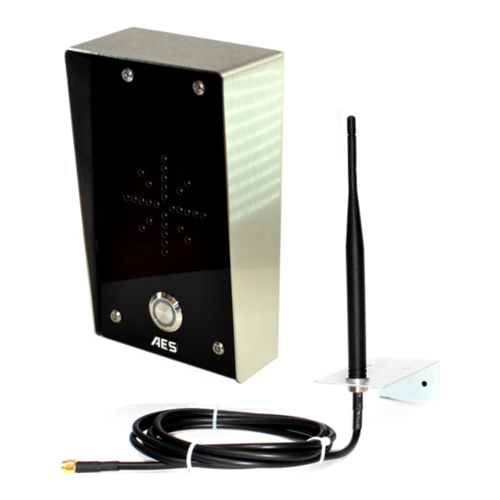
Call Button
Optional keypad
module
ARCHITECTURAL
HOODED
MODEL
MODEL
Hinge front door
Side View
Speech
Unit
200mm
min
4-5 feet
Entrance
minimum
Pillar
Side View
Wiring
Antenna connector.
Finger tighten only!
Power LED
GSM LED
GSM
Searching
modem
close
Network found
open
CPU LED
Standby
Busy
12v dc
Output
Exit button
Note: PSU
should be
Tamper
located
N/C
within 2
meters (6
feet)
N/O
OUT3
COM
N/C
-
+
12-24v
OUT1 OUT2
dc
Keypad Connections
(only keypad models)
11) Allow 20-30 seconds for the unit to boot up and detect the network.
Once successful connection has been made, the unit will sound a
confirmation tone and the GSM LED will begin flashing.
If there is a fault or problem, the unit will emit a series of bleeps or warning
tones. If this occurs, check...
1) That the SIM card has been activated and has credit.
2) That the SIM card does not require a PIN code, disable this in a phone.
3) That the SIM card can make and received a call on a phone.
4) If the SIM card was purchased with a phone, that it is not locked to that
phone. Call the network operator to check.
5) Switch off power, remove and reseat the SIM card and try again.
LocksOnline Ltd
Installation Manual
3) Remove the top two security
screws as shown. Do NOT remove
the bottom screws.
The front door will hinge downwards
to allow access for mounting holes
and connection terminals.
Note: The protective film on the front
of the intercom should not be removed
until fully installed.
4) Use appropriate wall fixings. 8-
10mm anchors, 75mm deep with M5
screw are recommended as a
minimum.
5) Install the antenna as high as
possible on the top of the pillar to
ensure line of sight in all directions for
best possible reception.
Keep antenna high as possible, and
above electronics + audio equipment
to eliminate interference
6) Carefully follow the
wiring instructions.
Additional wiring
suggestions for electric
strike lock and magnetic
lock are shown overleaf.
SIM card
SIM card
holder
7) Register your SIM card
with the network, and check
it works in a mobile phone
first. If you are using a Pre-
pay or Pay&Go SIM, it will
Optional
input limit
need topped up first. Your
switch
SIM should be GSM
from gate
compatible.
INT Lock
8) Ensure the
power is OFF
O/P1 inhib
before inserting the SIM card.
Sense
(-)GND
9)
Carefully slide the SIM
DU out
holder
in the OPEN direction,
K or A
insert the SIM, and slide in the
CLOSED direction to lock it in
place.
Do NOT Force or use a
screwdriver!
10) After a final check of
wiring, switch on the power.
Tel +44 (0) 845 230 02 01 |
Programming Quick Start Guide
Programming is carried out by sending SMS texts to the unit.
1) First check reception. Send the following SMS to the unit...
The unit should reply SIGNAL LEVEL = ?
Where ? will be between 1 and 31
Below 14 can cause problems with relay
operation, or no voice from the gate to the
house. Take action to improve reception.
2) Program the numbers you wish the unit to dial when the call button is
pressed, up to a maximum of 3 numbers. Each SMS must start with the pass
code, default 1234, in the following format *12*1234#, followed immediately
by a command. E.g to program the telephone number 0987654321, enter
the following SMS..
*12*1234#110987654321#
Pass code
Data
Function code
3) It is recommended to change the "no answer" time if there is more than 1
number stored. This stops the unit ringing a number after a set time, and can
be used to prevent voicemail answering the call. Send the following SMS..
*12*1234#52??#
Where ?? can be 2 digits from 10-99 seconds, default is 20.
The unit can allow up to 100 telephone numbers to be stored, for users to
be able to ring the system for automatic entry. This uses caller ID like a
phone to determine the identity of the caller. First, the unit must know what
country it is operating in.
4) Program the country code as follows..
Where ?? can be 1-3 digits. For uk, insert 44, for Ireland 353, for
*12*1234#71??#
USA insert 1. Do not use any leading zeros.
5) Enter the telephone numbers required to have access control. Do not enter
country code, just the complete number as you would dial it..
*12*1234#720987654321#
USA customers – For some networks, you may need to enter the numbers with the long distance 1
before area code, then the number. E.g. 1-702-555-1234. Try it with and without to see method works.
Additional Programming Parameters
Code
Description
01????#
Change programming password.
Change access control password (allows users not in caller ID list
02????#
to call intercom and use pass code to activate relay).
03????#
Change monitoring mode password (dial to listen in mode)
1n*#
Delete a button calling number, where
3?#
Speaker volume. Where
4?#
Microphone volume. Where
51?#
Relay time. Where
53??#
Max call time. Where
Max monitoring time (for listen in mode when calling the intercom)
55??#
00-60 mins. 00 = no limit.
Unit can call or SMS service number by set duration to prevent
57??#
SIM card deactivation if seldom used. 00-60 days. 00 = no inform.
Choose between scheduled call to service number or send SMS to
58?#
service number. ?=1 for SMS, 2 for call.
Store service number to receive scheduled SMS or call from
77number#
intercom.
77*#
Delete service number.
Dial in mode for withheld numbers or non stored numbers. 1 =
65?#
answer the call & wait for pass code. 2 = answer the call &
automatically activate 2 way speech.
73??#
Delete phone number for caller ID access.
73*#
Delete all phone numbers for caller ID access.
999#
Restore defaults
Check stored numbers. Note: no pass code needed for this
*21#
command. O = dial out number. I = Dial in number.
Remember to begin each new SMS with pass code *12*1234#
Email enquiries@locksonline.co.uk
1-12
13-20
Poor
Medium
Up to 3 numbers can be sent together in a single SMS as
follows..
*12*1234#11tel.number1#12tel.number2#13tel.number3#
11 = Telephone number 1
12 = Telephone number 2
13 = Telephone number 3
Up to 3 numbers can be sent together in the same SMS. Just
add 72 then the number, then # each time. The pass code only
needs to be put at the beginning of each new messge.
n
= number 1,2 or 3.
?
= level 0 - 3
?
= level 0 - 3
?
= 1-9999 seconds.
???
= 005-999 seconds (3 digit code)
www.locksonline.co.uk
*20#
21-31
Good
Default
1234
5678
1212
N/A
3
3
1 sec
60 sec
10 min
00
1
N/A
N/A
1
N/A
N/A
N/A
N/A
Advertisement

Subscribe to Our Youtube Channel
Related Manuals for AES GSM-3AB


Summary of Contents for AES GSM-3AB
- Page 1 GSM-3AB & ABK Installation Manual GSM-3HB & HBK V3.5 (1200 keypad) Installation Programming Quick Start Guide 1) Before you install this equipment, please read this full manual. Programming is carried out by sending SMS texts to the unit. 2) Ensure that there is good network reception at the location where it *20# 1) First check reception.
- Page 2 Keypad Programming (only ABK models) Programming SUPER user code LED indicators Super user code is an optional feature which allows the same code to operate outputs 1, 2 or 3. ON when incorrect codes entered and outputs are locked out. GREEN when output 1 activated.
- Page 3 User Manual For GSM-3AB / ABK / HB / HBK Wireless Intercom This GSM intercom system will call up to 3 telephone numbers in sequence when the call button is pressed. There are several modes of operation depending on how the unit has been programmed by your installer. The following instructions will assume default programming.
- Page 4 Sending SMS Commands All of the features shown on the Android app are also available for non Android users, or non smart phone users. You can simply send the same SMS commands manually to the intercom as detailed below... Momentary trigger output relay (default user pass code 5678) *33*5678# *34*5678# Latch output relay (default user pass code 5678)
Need help?
Do you have a question about the GSM-3AB and is the answer not in the manual?
Questions and answers