
Related Manuals for EPC EPC9066


Summary of Contents for EPC EPC9066
- Page 1 Development Board EPC9066 Quick Start Guide EPC8004 40 V Half Bridge with Sync FET Bootstrap Gate Drive...
- Page 2 *Assumes inductive load, maximum current depends on die temperature – actual maximum current with be subject to switching frequency, bus voltage and thermals. The EPC9066 development board is 2” x 1.5” and has two EPC8004 eGaN # Limited by time needed to ‘refresh’ high side bootstrap supply voltage.
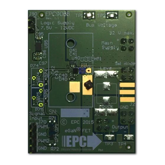
- Page 3 HF output Gate drive regulator DC output Buck Logic and dead-time adjust Bypass PGND Figure 1: Block diagram of EPC9066 development board Main voltage measurement 7.5 – 12 V Switch-node oscilloscope probe supply (note polarity) Ground post 32 V DCmax...
- Page 4 125°C. management requirements. The EPC9066 is intended for bench NOTE. The EPC9066 development board does not have any current or thermal evaluation with low ambient temperature and convection cooling. protection on board.
- Page 5 QUICK START GUIDE EPC9066 EPC – EFFICIENT POWER CONVERSION CORPORATION | WWW.EPC-CO.COM | COPYRIGHT 2016 | |PAGE 5...
- Page 6 Demonstration Board Notification The EPC9066 board is intended for product evaluation purposes only and is not intended for commercial use. As an evaluation tool, it is not designed for compliance with the European Union directive on electromagnetic compatibility or any other such directives or regulations. As board builds are at times subject to product availability, it is possible that boards may contain components or assembly materials that are not RoHS compliant.
Need help?
Do you have a question about the EPC9066 and is the answer not in the manual?
Questions and answers