
Related Manuals for EPC EPC9144


Summary of Contents for EPC EPC9144
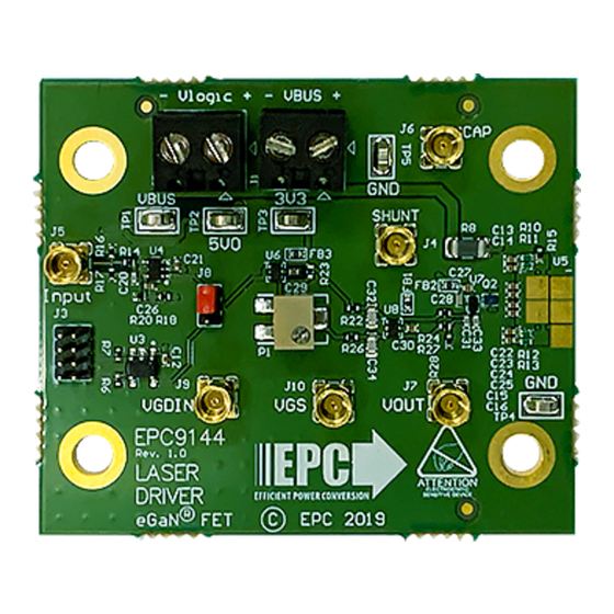
- Page 1 Development Board EPC9144 Quick Start Guide EPC2216 15 V High Current Pulsed Laser Diode Driver Revision 1.0...
-
Page 2: Setup And Operation
5. With power off, connect the signal pulse generator to the input J5. J5 range and observe the system behavior. is terminated with 50 Ω on the EPC9144, and is designed for a 3.3 V 11. For shutdown, please follow steps in reverse. -
Page 3: Operating Principle
U2. After the narrow pulse generator The EPC9144 can be used as is to mount a laser diode or other load. output goes low, Q1 turns off. If there is current remaining in the power Figure 3 highlights the output pad locations. -
Page 4: Measurement Considerations
The recommended procedure for the use of the interposer is the following: Left 1. Apply solder paste to the U2 pads on the EPC9144 PCB. Breakaway V-grooves 2. Apply solder paste to the appropriate pads on the top side of the interposer. - Page 5 Bus capacitor voltage (VCHARGE on 41 V/V Clamping diodes schematic) The EPC9144 shipped configured as a dual edge control driver. SHUNT Shunt voltage Not used When the FET Q1 is turned off, energy stored in the stray power loop inductance can cause a Q1 drain voltage spike to exceed the device...
- Page 6 1 F, 4.7 F, 1 F, 50 V 25 V 50 V TLV75533PDRVR HOLE1 HOLE2 HOLE3 HOLE4 4-40 4-40 4-40 4-40 Local Fiducials Figure 7: Schematic EPC9144 (part1) EPC – THE LEADER IN GaN TECHNOLOGY | WWW.EPC-CO.COM | COPYRIGHT 2019 |...
- Page 7 50 V 8 pF, 50 V VGDIN GD prop delay i Gate drive input sense Gate voltage sense GD prop delay Z50 single core Z50 single core MMCX SMD MMCX SMD probe probe loop loop Figure 8: Schematic EPC9144 (part 2)
- Page 8 QUICK START GUIDE Demonstration System EPC9144 Table 3: Bill of Materials - EPC9144 Item Quantity Reference Part Description Manufacturer Manufacturer Part # C6, C7, C8, C9, C11 Capacitor, 1 µF, 25 V, X7R 0603 Taiyo Yuden UMK107AB7105KA-T C1, C2, C3, C4 Capacitor, 1 µF, 100 V, X7S 0805...
- Page 9 The EPC9144 board is intended for product evaluation purposes only. It is not intended for commercial use nor is it FCC approved for resale. Replace components on the Evaluation Board only with those parts shown on the parts list (or Bill of Materials) in the Quick Start Guide. Contact an authorized EPC representative with any questions. This board is intended to be used by certified professionals, in a lab environment, following proper safety procedures.
Need help?
Do you have a question about the EPC9144 and is the answer not in the manual?
Questions and answers