Advertisement
Quick Links
Advertisement

Related Manuals for EPC EPC9101


Summary of Contents for EPC EPC9101
- Page 1 Demonstration Board EPC9101 Quick Start Guide EPC2014 + EPC2015 1 MHz Buck Converter...
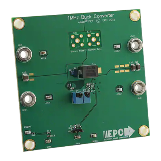
- Page 2 DESCRIPTION www.epc-co.com The EPC9101 demonstration board is a 1.2 V output, 1 MHz buck The EPC9101 demonstration board is 3” square and contains converter with an 20 A maximum output current and 8 V to 24 a fully closed loop buck converter. The power stage is a single V input voltage range.
-
Page 3: Quick Start Procedure
Quick Start Procedure Demonstration board EPC9101 is easy to set up to evaluate the performance of the EPC2014 and EPC2015 eGaN FETs and LM5113 driver. Refer to Figure 2 for proper connect and measurement setup and follow the procedure below: 1. - Page 4 Dead-Time Adjust Single sided layout power stage Minimize loop Place probe tip on pad Figure 1: Block Diagram of EPC9101 Demonstration Board Figure 3: Proper Measurement of Switch Node or Gate Voltage < 20 V < 24 V Active Load Supply –...
-
Page 5: Thermal Considerations
THERMAL CONSIDERATIONS The EPC9101 demonstration board thermal images for steady state full load operation are shown in Figure 6. The EPC9101 is intended for bench evaluation with low ambient temperature and forced air cooling for higher currents. Care must be taken to not exceed the absolute maximum die temperature of 125°C... - Page 6 Schottky Diode, 30V Diodes Inc., SDM03U40-7 J1, J2, J3, J4 Banana Jack Keystone, 575-4 Inductor, 270nH Coilcraft, SLC1175-271ME eGaN® FET EPC, EPC2014 eGaN® FET EPC, EPC2015 Resistor, 15.0K, 1%, 1/8W Stackpole, RMCF0603FT15K0 R3, R4, R10 Resistor, 10.0K, 1%, 1/10W Stackpole, RMCF0603FT10K0...
- Page 7 R2 15k Vrng PGND 22pF EPC2015 IntVCC 0 Ohm SDM03U40 R15 680 R9 2.2 R22 47 47uF, 10V MODE LM5113TM 0.1uF, 25V Zero 39.2k 100pF 0.1uF, 25V Optional 100pF NC7SZ00L6X 4.7uF, 10V Keystone 5015 Demonstration Board – EPC9101 Schematic Rev. 2.0...
- Page 8 Demonstration Board Notification The EPC9101 board is intended for product evaluation purposes only and is not intended for commercial use. As an evaluation tool, it is not designed for compliance with the European Union directive on electromagnetic compatibility or any other such directives or regulations. As board builds are at times subject to product availability, it is possible that boards may contain components or assembly materials that are not RoHS compliant.
Need help?
Do you have a question about the EPC9101 and is the answer not in the manual?
Questions and answers