
Related Manuals for EPC EPC9147C


Summary of Contents for EPC EPC9147C
- Page 1 Development Board EPC9147C Quick Start Guide Motor Drive Controller Interface Board – STMicroelectronics STM32 Nucleo Revision 2.2...
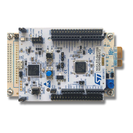
- Page 2 FET/IC 3-phase inverter using sensor-less field oriented control with space vector pulse width modulation. Figure 1 shows an overview of the EPC9147C board detailing connections and various human interfaces that measures 120 mm x 71 mm (L x W).
- Page 3 ST Nucleo board – press this button once to start the motor and press it again to stop the motor. • Speed potentiometer on EPC9147C – This knob can be used to change the motor speed. By default, the potentiometer is not interfaced in original ST firmware, so it is up to the customer to modify the ST firmware to interface the potentiometer to use it as target speed setting analog interface.
- Page 4 Internal/External 3.3 V Power Jumper Setting The EPC9147C is provided with a jumper (J7) that, when it is mounted (by default), allows the 3.3 V power supply to be fed by the Power Board. If Jumper J7 is not mounted, the EPC9147C 3.3 V (and the ST Nucleo 3.3V) power must be supplied by an external 3.3 V power supply connected to the connector J6.
-
Page 5: Connection Details
EPC9147C Motor Drive Controller Interface Board Compatible Motor Drive Inverters A list of motor drive inverter power boards compatible to the EPC9147C is given in table 2. Table 2: Compatible eGaN FET/IC motor driver inverters to the EPC9147C Motor Drive Inverter Board Number... - Page 6 QUICK START GUIDE EPC9147C Motor Drive Controller Interface Board PROGRAMMING WITH .elf FILE The ST Nucleo board comes with an onboard programmer debugger. Connect the CN1 connector to a USB port of your computer and use the STM32 CubeProgrammer software. The CN1 connector requires a Micro B USB male cable. The STM32CubeProgrammer software can be downloaded from ST’s’...
-
Page 7: Quick Start Procedure
Pin # Connector The EPC9147C is provided with an extra function port (J2) that can be used to expand functionality to the board. Table 6 provides the pin allocation map for the expansion port. The usage of the expansion port depends on official ST firmware. - Page 8 ST MOTOR CONTROL WORKBENCH Download from EPC power board web page the proper .zip archive that contains the ST Motor Control Workbench project. Unzip the archive by placing the .stmcx file and the contained directory in a folder in your computer. E.g., for EPC9145 power board, the project file name is G431- EPC9145-DummyNema34_50k_100n.zip, and it contains a file G431-EPC9145-DummyNema34_50k_100n.stmcx and a directory named G431-...
- Page 9 QUICK START GUIDE EPC9147C Motor Drive Controller Interface Board Project generation dialog box will appear. Verify it matches Figure 12’s settings and then click Generate. Figure 12: STM32CubeMX Code Generation dialog box Once the Generation is complete, click Open Folder button and then click the Close button.
- Page 10 QUICK START GUIDE EPC9147C Motor Drive Controller Interface Board In the explorer window where the generated code folder is shown, as in Figure 14, open the folder named STM32CubeIDE. Figure 14: Generated code folder Inside the STM32CubeIDE folder, double click the .project file.
- Page 11 Click the Terminate button as in Figure 18 and disconnect the USB cable. The STM32CubeIDE program can be closed. The ST Nucleo Board in the EPC9147C is now ready to run the motor and you can follow the steps described in the quick start procedure paragraph.
- Page 12 QUICK START GUIDE EPC9147C Motor Drive Controller Interface Board Connect the USB cable to the PC and power up the 48 V to the power board. Click on the Connect button. Figure 20: Connect button Wait for the successful connection message (Figure 21).
- Page 13 QUICK START GUIDE EPC9147C Motor Drive Controller Interface Board Table 5: Bill of Materials Item Qty Reference Part Description Manufacturer Part # CAP CER 0.1 μF 16 V X7R 0603 0603YC104KAT2A C2, C3, C4 CAP CER 0.1 μF 16 V X7R 0603...
- Page 14 EMPTY 0603 0603 0603 Nucleo Board Connection 100 nF 16 V 100 nF 16 V 100 nF 16 V GNDA GNDA GNDA 8834 8834 8834 8834 Board Stando s PCB Fiducial PCB Fiducial PCB Fiducial Figure 23: EPC9147C Main schematic...
-
Page 15: Visit Our Website
The EPC9147C board is intended for product evaluation purposes only. It is not intended for commercial use nor is it FCC approved for resale. Replace components on the Evaluation Board only with those parts shown on the parts list (or Bill of Materials) in the Quick Start Guide. Contact an authorized EPC representative with any questions. This board is intended to be used by certified professionals, in a lab environment, following proper safety procedures.
Need help?
Do you have a question about the EPC9147C and is the answer not in the manual?
Questions and answers