
Related Manuals for EPC EPC9097


Summary of Contents for EPC EPC9097
- Page 1 Development Board EPC9097 Quick Start Guide 100 V Half-bridge with Gate Drive, Using EPC2204 Revision 2.0...
- Page 2 QUICK START GUIDE EPC9097 DESCRIPTION Table 1: Performance Summary (T = 25°C) EPC9097 The EPC9097 development board is a 100 V maximum device voltage, Symbol Parameter Conditions Min Nominal Max Units 20|A maximum output current, half bridge featuring the EPC2204 GaN Gate Drive Regulator field effect transistor (FET).
-
Page 3: Bypass Settings
Buck Boost Dual input The EPC9097 development board is easy to set up as buck or boost converter to evaluate the performance of the EPC2204 eGaN FETs. This board includes a logic PWM input signal polarity changer used to ensure... - Page 4 Figure 6: (a) Single-PWM input buck converter (b) Dual-PWM input buck converter configurations showing the supply, anti-parallel diodes, output capacitor, inductor, PWM, and load connections with corresponding jumper positions. EPC – POWER CONVERSION TECHNOLOGY LEADER | EPC-CO.COM | ©2021 |...
- Page 5 PWM, and load connections with corresponding jumper settings. behavior, efficiency, and other parameters. Observe device temperature for operational limits. 9. For shutdown, please follow steps in reverse. EPC – POWER CONVERSION TECHNOLOGY LEADER | EPC-CO.COM | ©2021 |...
- Page 6 = 48 V, V = 12 V, I = 10 A, f = 500 kHz, L = 2.2 H Figure 9: Typical switch-node waveform when operated as a buck converter EPC – POWER CONVERSION TECHNOLOGY LEADER | EPC-CO.COM | ©2021 |...
- Page 7 EPC recommends t-Global P/N: TG-X 500 µm for the thermal interface material. Figure 10: Details for attaching a heatsink to the EPC9097 board. The mechanical spacers will accept M2 x 0.4 mm (a) 3D perspective, (b) top view details.
- Page 8 Molex 734152063 2 port Euro Block connector Wurth 691216410002 J22, J33 100 mil 1x2 male header Tyco 4-103185-0-02 GenericOutputInductor R11, R22 0 Ω Stackpole RMCF0402ZT0R00 4.7 Ω Panasonic ERJ-2GEJ4R7X EPC – POWER CONVERSION TECHNOLOGY LEADER | EPC-CO.COM | ©2021 |...
- Page 9 QUICK START GUIDE EPC9097 EPC – POWER CONVERSION TECHNOLOGY LEADER | EPC-CO.COM | ©2021 |...
- Page 10 QUICK START GUIDE EPC9097 EPC – POWER CONVERSION TECHNOLOGY LEADER | EPC-CO.COM | ©2021 | | 10...
- Page 11 QUICK START GUIDE EPC9097 EPC – POWER CONVERSION TECHNOLOGY LEADER | EPC-CO.COM | ©2021 | | 11...
- Page 12 QUICK START GUIDE EPC9097 EPC – POWER CONVERSION TECHNOLOGY LEADER | EPC-CO.COM | ©2021 | | 12...
- Page 13 QUICK START GUIDE EPC9097 EPC – POWER CONVERSION TECHNOLOGY LEADER | EPC-CO.COM | ©2021 | | 13...
-
Page 14: Visit Our Website
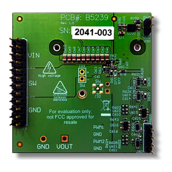
The EPC9097 board is intended for product evaluation purposes only. It is not intended for commercial use nor is it FCC approved for resale. Replace components on the Evaluation Board only with those parts shown on the parts list (or Bill of Materials) in the Quick Start Guide. Contact an authorized EPC representative with any questions. This board is intended to be used by certified professionals, in a lab environment, following proper safety procedures.
Need help?
Do you have a question about the EPC9097 and is the answer not in the manual?
Questions and answers