
Related Manuals for EPC EPC9147A


Summary of Contents for EPC EPC9147A
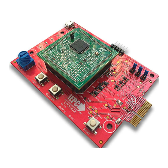
- Page 1 Development Board EPC9147A Quick Start Guide Motor Drive Controller Interface board – Microchip DSP Revision 2.0...
- Page 2 QUICK START GUIDE EPC9147A Interface Board for Motor Drive Board DESCRIPTION The EPC9147A board is an interface board that accepts the Microchip MA330031-2 Plug-In-Module (PIM), that is fitted with the dsPIC33EP256MC506 Digital Signal Processor (DSP), and interfaces to a 3-phase eGaN® FET/IC motor drive inverter board.
- Page 3 EPC9147A Interface Board for Motor Drive Board The EPC9147A is includes a standard Microchip compatible programming port (J4), I2C expansion port (J8) and, a 40-pin card edge connector (J2) that interfaces the PWM, analog feedback signal, errors states and 3.3 V power to the motor drive inverter board as shown in figure 2.
-
Page 4: Test Points
Motor Phase Monitoring Jumper Settings Motor Phase Voltage 1 Shaft Encoder A Current 1 The EPC9147A is provided with a set of jumpers that can be used to change Motor Phase Motor Phase Voltage 2 Shaft Encoder B Current 2 the monitoring connections. -
Page 5: Connection Details
Compatible Motor Drive Inverters A list of compatible motor drive inverter to the EPC9147A is given in table 2. Check EPC9147A web page for updates on additional compatible converters. Table 2: Compatible eGaN FET/IC motor driver inverters to the EPC9147A... - Page 6 QUICK START GUIDE EPC9147A Interface Board for Motor Drive Board Programming with HEX file Download the latest MPLAB® X IPE from Microchip website and follow the five steps below: https://www.microchip.com/mplab/mplab-integrated-programming-environment 1. Enable Advanced Mode: 5. Erase device, and then program device: 2.
-
Page 7: Quick Start Procedure
Motor Name Dummy programming port (JX) and select the Program Icon. Make sure that Part Number Dummy the ICD can power up the EPC9147A and that the EPC9147A is not Additional Info rshunt=1.5 connected to other power supply. MicrochipDIRECT Part Number Note: Every time you change Motor or load (e.g. - Page 8 QUICK START GUIDE EPC9147A Interface Board for Motor Drive Board Table 1: Bill of Materials Item Qty Reference Part Description Manufacturer Part # C5, C7 33 pF Yageo CC0603JRNPO9BN330 C13, C14, C15 10 μF Murata GRM188R61C106MA73D C22, C23 10 μF...
- Page 9 R2 6 PIM_ PG ood_E N PG ood_E N V _M1 PIM_ V _M1 0603 0603 Fiducial Local Fiducial Local Fiducial Local ProbePad 0.1 W 0.1 W 60 mil User Interface EMPTY EMPTY Optional Mapping Figure 4: EPC9147A Main schematic...
- Page 10 0402 1/10 W 1/10 W 1/10 W 1/10 W D301 D302 D303 D304 LTST-C193KRKT-5A LTST-C193KSKT-5A LTST-C193TBKT-5A LTST-C193KGKT-5A 0603 Red 0603 Yellow 0603 Bl ue 0603 G reen Error Debug 1 Debug 2 Power Indicators Figure 5: EPC9147A Human Interface schematic...
- Page 11 Use ADuM1201 for UART (Default) 100 nF 25 V GNDF GNDF Do Not Connect Use ADuM1250 forI2C GNDF Shield GNDF R5 01 C501 0402 0402 4.7 k 0.1 W 100 nF 25 V GNDF GNDF GNDF GNDF Figure 6: EPC9147A USB schematic...
- Page 12 0402 0402 30 k 1/16 W 1 nF 50 V OUT PU T IN PU T 0402 L MV 7235M7/NOPB 1 k 1/16 W 0402 1 nF 50 V 0402 100 nF 25 V Figure 7: EPC9147A Over-current Detect schematic...
- Page 13 0402 0402 10 k 1/16 W 100 nF 25 V V _M1 Vout1 0402 V in1 U212 1/16 W OPA320AIDBVT 0402 100 nF 25 V C212 0402 100 nF 25 V Figure 8: EPC9147A Phases and Neutral Voltage Feedback schematic...
Need help?
Do you have a question about the EPC9147A and is the answer not in the manual?
Questions and answers