
Related Manuals for Lectrosonics DM1612


Summary of Contents for Lectrosonics DM1612
- Page 1 Reference Manual for Operation Reference Manual DM Series Digital Audio Processors models DM812, DM1612, DM1624 www.lectrosonics.com Rio Rancho, NM – USA...
- Page 2 DM Series Digital Matrix Processors...
-
Page 3: Important Safety Instructions
Reference Manual for Operation IMPORTANT SAFETY INSTRUCTIONS This symbol, wherever it appears, alerts you to the presence of uninsulated dangerous voltage inside the enclosure -- voltage that may be sufficient to constitute a risk of shock. This symbol, wherever it appears, alerts you to important operating and maintenance instructions in the accompanying literature. - Page 4 DM Series Digital Matrix Processors...
-
Page 5: Table Of Contents
Reference Manual for Operation TABLE OF CONTENTS General Overview ............................9 Signal Flow ..................................9 Input Processing ................................11 Input Gain ................................11 Delay ..................................11 Filters ..................................11 ADFE Filters ................................. 11 Compressor ................................11 Digital Matrix ................................. 12 Automixer Cell .............................. - Page 6 DM Series Digital Matrix Processors TABLE OF CONTENTS Serial Port Speed Adjustment ............................26 Leaving the Top Menu ..............................26 TopMenu - CmdView ............................26 TopMenu - SerPort ............................... 26 TopMenu - EXIT ..............................26 Installing LecNet2™ Software and USB Driver ..................27 Installing LecNet2™...
- Page 7 Reference Manual for Operation TABLE OF CONTENTS rpingnmin (rear panel audio input gain minimum) ....................41 Serial Interface & Control Commands (cont'd) ..................42 rpingnpre (rear panel audio input gain preset) ..................... 42 rpingnst (rear panel input gain step change) ......................42 rpoutgn (rear panel audio output gain) .........................
- Page 8 DM Series Digital Matrix Processors...
-
Page 9: General Overview
Reference Manual for Operation General Overview As digital technology continues to advance in a variety the same signal processing functions, and vary only by of markets and products, considerable benefits also the number of audio inputs and outputs available. evolve in audio processing systems for installed sound Each input channel includes a high quality analog systems that employ multiple microphones and loud- preamplifier, with digital and analog level control to... - Page 10 DM Series Digital Matrix Processors Prog I/O Conn LecNet 2 Conn Front & Rear 2 x DB25 1/8 '' Jack USB B Conn Signal Processing Out 1 Prog I/O RS-232 Signal Processing Port Port Port Out 2 Signal Processing Out 3 Signal Processing Out 4 Micro...
-
Page 11: Input Processing
Reference Manual for Operation Input Processing Each input channel provides individual stages for gain, ADFE Filters delay, filtering and compression as shown in the illustra- Six ADFE (automatic digital feedback eliminator) filters tion. Levels can be set up with the front panel LCD or are provided on each input to suppress acoustic feed- with the software GUI provided with the units. -
Page 12: Digital Matrix
DM Series Digital Matrix Processors Digital Matrix The digital matrix provides signal routing and communi- Mixing Mode cation with other devices in the system, and applies The automatic mixing algorithm applies a patented gain automatic mixing and level control. A single crosspoint proportional algorithm* that allows each input assigned is shown here to illustrate the elegance of the matrix. -
Page 13: Output Processing
Reference Manual for Operation Output Processing Each output can receive signals from either the matrix, Mic/line Output Channels the pink noise generator, the tone generator, or from the Some outputs include an attenuator to reduce the master unit DANI source (if it is operating in a multi-unit output level from line to mic level. -
Page 14: Output Signal Processing Stages
DM Series Digital Matrix Processors Output Signal Processing Stages Compressor and Limiter Each output channel provides a delay, nine filters, plus a A versatile compressor and limiter are provided at each compressor and limiter to idealize the channel for its output to control the average level and dynamics of the function in the sound system. -
Page 15: Hardware Front Panels
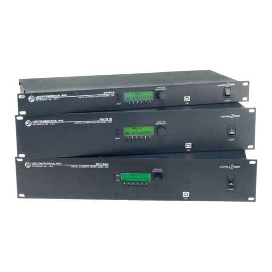
DM1624 - 16 inputs, 24 outputs DM1612 - 16 inputs, 12 outputs DM812 - 8 inputs, 12 outputs Rio Rancho, NM – USA... -
Page 16: Hardware Rear Panels
90–240VAC / 30W Serial Number RS-232 No User Serviceable Parts Inside Here MADE IN U .S.A. DM1612 - 16 inputs, 12 outputs 1 - GND 6 - IN 20 11 - OUT 13 16 - IN 15 21 - OUT 10 U.S. -
Page 17: Lcd Interface
Reference Manual for Operation LCD Interface Operation with Front Panel Controls Some adjustments, such as levels and mute activity, can Direct interaction with the processor is provided using be made to DM Series processors without a computer the front panel buttons, the rotary encoder knob and the using the front panel LCD interface. -
Page 18: General Overview - Menus And Screens
DM Series Digital Matrix Processors General Overview - Menus and Screens Top Menu Top Menu When the encoder knob is pressed at the the model number screen, the screen defaults to the TopMenu. Rotate the knob to select the menu item. The Setup item is selected in this ex- ample. -
Page 19: The "Back" Button
Reference Manual for Operation Input Setup Input Select Select IN to choose the desired input channel. The channel number in the upper right hand section of the screen will be highlighted. Rotate the encoder knob to select the input channel and press it to accept the selection. -
Page 20: Matrix Crosspoint Setup Screens
DM Series Digital Matrix Processors Matrix Crosspoint Setup Screens Setup - Matrix Navigate to the Setup menu and rotate the encoder knob to select Matrix, as shown in this example. Press the encoder knob to move to the Xpoint Setup (matrix crosspoint) setup screen. Xpoint Setup Menu Matrix crosspoints are configured from this screen, which contains settings for a single crosspoint. -
Page 21: Output Setup Screens
Reference Manual for Operation Output Setup Screens Setup - Outputs Navigate to the Setup screen and rotate the encoder knob to select Outputs, as shown in this example. Press the encoder knob to move to the Output Setup screen. Output Setup - Output Select Audio outputs are configured from this screen, which contains the settings for a single output channel. -
Page 22: Preset Setup Screens
DM Series Digital Matrix Processors Preset Setup Screens TopMenu - Presets Navigate to the Top Menu and rotate the encoder knob to select the Presets item as shown in this example. Press the encoder knob to move to the Preset Control screen. Preset Control Screens - Using the OK item on all screens Preset Control screens are different from the other screens. -
Page 23: Stacking Multiple Units
Reference Manual for Operation System Information TopMenu - SysInfo Navigate to the the SysInfo item on the Top Menu. Press the encoder knob to access the information screen. System Information Screen This screen provides the basic information about the unit and its present state in the system. -
Page 24: Locking Out The Front Panel Controls
DM Series Digital Matrix Processors Locking out the front panel controls TopMenu - LockSet Navigate to the Top Menu and select the LockSet menu item. Press the encoder knob to enter the Lock Setup screen. Lock Setup - Entering the Passcode The screen appears as in this example when LockSet is entered from the Top Menu, and the front panel controls are unlocked (enabled). -
Page 25: Changing The Passcode
Reference Manual for Operation Changing the Passcode Navigate to the Lock Setup Screen The status can be either UNLOCKED or LOCKED. Press the two buttons to the left of the display at the same time. PUSH FOR MENU/SELECT BACK Enter the existing passcode You will be prompted to enter the existing passcode when the word Old: appears on the screen. -
Page 26: Command View Screen
DM Series Digital Matrix Processors Command View Screen TopMenu - CmdView A convenient utility screen is provided assist in verifying correct serial commands have been sent to the unit. Navigate to the CmdView item on the Top Menu and press the encoder knob. The Command View screen shows a rolling list of the serial commands as they arrive in the unit. -
Page 27: Installing Lecnet2™ Software And Usb Driver
Reference Manual for Operation ™ Installing LecNet2 Software and USB Driver Part of the LecNet2 software package is the VR Panel First time installation for the Venue Receiver. This Graphic User Interface When a Lecnet2 device is connected to the PC for the (GUI) is designed to allow easy setup and monitoring of very first time, the Windows Found New Hardware the Venue Receiver using a computer system running... -
Page 28: Installation Additional Venue Receivers (Or Lecnet2 Devices)
DM Series Digital Matrix Processors 3. When the driver installation is complete, the 5. When the driver installation is complete, the final page of the Wizard appears. Click final page of the Wizard appears. Click Finish. It is now possible to connect to the Finish to complete the Lecnet2 USB driver Lecnet2 device. -
Page 29: Usb Driver Installation (Windows 2000)
Reference Manual for Operation USB Driver Installation (Windows 2000) First Time Installation When a Lecnet2 device is connected to the PC for the very first time, the Windows Found New Hardware Wizard automatically opens. Use the following proce- dure to install the Lecnet2 USB driver using the Wizard. 1. -
Page 30: Firmware Updates
DM Series Digital Matrix Processors Firmware Updates Using the Update Wizard 2. The first page of the Wizard displays instructions for the process of forcing the The control panel can be used to download firmware DM1624 into update mode. Follow them updates to the DM1624. - Page 31 Reference Manual for Operation 4. Here you may type in the path to the update Click Next to move on to the PROCEED file, or click on the “browse” button next to the WITH FIRMWARE UPDATE page: filename field. This opens the Select DM1624 update file dialog: Click Start Update to begin the firmware update.
- Page 32 DM Series Digital Matrix Processors This is followed by the DSP firmware update. Follow the instructions in the message to The text over the progress bar indicates verify that the DM1624 restarts with the which stage is in progress. updated firmware version. Click OK to dismiss the message.
-
Page 33: Serial Interface & Control Commands
Reference Manual for Operation Serial Interface & Control Commands Serial commands are delivered to the unit via the USB DM1624 Audio Input Commands or RS-232 interfaces to allow remote control of the inact Audio input activity status device. The command language is extremely simple to incl Audio input clipping status ease the task of programming. -
Page 34: Serial Interface & Control Commands (Cont'd)
DM Series Digital Matrix Processors Serial Interface & Control Commands (cont'd) address is wildcarded, then the data type is an array of inlb (input channel label) integer of size 16. In this case the value 9999 may be This command may be used as a query to read the used in an update to indicate that a particular input input channel text label, or as an update to set the label. -
Page 35: Serial Interface & Control Commands (Cont'd)
Reference Manual for Operation Serial Interface & Control Commands (cont'd) inmttog (input mute toggle) DM1624 Matrix Crosspoint Commands This command may be used as a simple comand to xpgn Matrix crosspoint gain toggle the input channel mute status. The input channel xpmode Matrix crosspoint mix mode is specified by using the address syntax. -
Page 36: Serial Interface & Control Commands (Cont'd)
DM Series Digital Matrix Processors Serial Interface & Control Commands (cont'd) crosspoint mix mode is to remain unchanged by the DM1624 Audio Output Commands command. outdel Audio output delay Examples: outgn Audio output gain REQUEST RESPONSE outlb Audio output channel label QUERY xpmode(5,9)? OK 3 outlv... -
Page 37: Serial Interface & Control Commands (Cont'd)
Reference Manual for Operation Serial Interface & Control Commands (cont'd) outlb (output channel label) Examples: This command may be used as a query to read the REQUEST RESPONSE output channel text label, or as an update to set the QUERY outmt(19)? OK 1 label. -
Page 38: Serial Interface & Control Commands (Cont'd)
DM Series Digital Matrix Processors Serial Interface & Control Commands (cont'd) DM1624 Input Compressor Commands incprat (input compressor ratio) This command may be used as a query to read the incpatt Input compressor attack time ratio, or as an update to set the ratio. The input channel incpgn Input compressor gain is specified by using the address syntax. -
Page 39: Serial Interface & Control Commands (Cont'd)
Reference Manual for Operation Serial Interface & Control Commands (cont'd) DM1624 Output Compressor Commands outcprat (output compressor ratio) This command may be used as a query to read the outcpatt Output compressor attack time ratio, or as an update to set the ratio. The output chan- outcpgn Output compressor gain nel is specified by using the address syntax. -
Page 40: Serial Interface & Control Commands (Cont'd)
DM Series Digital Matrix Processors Serial Interface & Control Commands (cont'd) DM1624 Output Limiter Commands DM1624 Programmable I/O Commands outlmatt Output limiter attack time prgin Programmable input state outlmrel Output limiter release time prgout Programmable output state outlmthr Output limiter threshold level prgoutht Programmable output hold time prgoutqt... -
Page 41: Serial Interface & Control Commands (Cont'd)
Reference Manual for Operation Serial Interface & Control Commands (cont'd) prgoutht (programmable output channel activity DM1624 Rear Panel Control Commands hold time) rpingn Rear panel audio input gain This command may be used as a query to read the hold rpingnmin Rear panel audio input gain minimum time, or as an update to set it. -
Page 42: Serial Interface & Control Commands (Cont'd)
DM Series Digital Matrix Processors Serial Interface & Control Commands (cont'd) Examples: Examples: REQUEST RESPONSE REQUEST RESPONSE QUERY rpingnmin? OK -30 QUERY rpoutgn(1)? OK -3 UPDATE rpingnmin=-15 QUERY rpoutgn(*)? OK {-13,-4,0,...,0,0,0} UPDATE rpoutgn(22)=0 rpingnpre (rear panel audio input gain preset) UPDATE This command may be used as a query to read the rear rpoutgn(*)={0,-5,0,...,99,99,-10} OK... -
Page 43: Serial Interface & Control Commands (Cont'd)
Reference Manual for Operation Serial Interface & Control Commands (cont'd) rprest (restore rear panel settings) DM1624 ADFE Commands This command may be used to restore the state of rear adfeen Automatic digital feedback elimination enable panel settings previously saved with the rpsave com- adfefil Automatic digital feedback elimination filter mand. -
Page 44: Serial Interface & Control Commands (Cont'd)
DM Series Digital Matrix Processors Serial Interface & Control Commands (cont'd) ADFE Filter Numbers Mapped to Center Frequencies 0 None 16 375 Hz 32 1031 Hz 48 2063 Hz 64 3750 Hz 80 6281 Hz 1 105 Hz 17 410 Hz 33 1090 Hz 49 2156 Hz 65 3891 Hz... -
Page 45: Macros And Macro Control
Reference Manual for Operation Macros and Macro Control About Macros The DM1624 can be remotely controlled using com- Queries, commands which request information from the mands sent over USB, a serial port, or a network DM1624, make no sense within a macro. connection. -
Page 46: Rear Panel Control - Hardware
DM Series Digital Matrix Processors Rear Panel Control - Hardware The DM processor has programmable inputs which An important application of the rear panel control can be used to control a wide variety of functions. interface is to manage what is called the rear panel Depending on the function assigned to them, these gain for input and output audio channels. - Page 47 Reference Manual for Operation Rio Rancho, NM – USA...
- Page 48 This warranty does not apply to used or demonstrator equipment. Should any defect develop, Lectrosonics, Inc. will, at our option, repair or replace any defective parts without charge for either parts or labor. If Lectrosonics, Inc. cannot correct the defect in your equipment, it will be replaced at no charge with a similar new item.
Need help?
Do you have a question about the DM1612 and is the answer not in the manual?
Questions and answers