Table of Contents
Advertisement
Quick Links
SPNTrio
Digital Conference Interface
Software and Hardware Installation and Setup
Fill in for your records:
Serial Number:
Purchase Date:
IMPORTANT
See page 15 for
Minimum Setup Requirements
INSTALLATION and STARTUP GUIDE
Visit the ASPEN Support web site:
www.lectrosonics.com/aspensupport/
Also link from the home page: www.lectrosonics.com
Rio Rancho, NM, USA
www.lectrosonics.com
Advertisement
Table of Contents

Related Manuals for Lectrosonics SPNTrio


Summary of Contents for Lectrosonics SPNTrio
- Page 1 Software and Hardware Installation and Setup IMPORTANT See page 15 for Minimum Setup Requirements Visit the ASPEN Support web site: www.lectrosonics.com/aspensupport/ Also link from the home page: www.lectrosonics.com Fill in for your records: Serial Number: Purchase Date: Rio Rancho, NM, USA www.lectrosonics.com...
-
Page 2: Important Safety Instructions
When a cart is used, use caution when moving the cart/ apparatus combination to avoid injury from tip-over. 13) Unplug this apparatus during lightning storms or when unused for long periods of time. LECTROSONICS, INC. -
Page 3: Table Of Contents
Installation and Startup Guide Table of Contents Important Safety Instructions................................2 Inspection of the Unit .....................................2 Introduction ......................................4 Front Panel ......................................5 Rear Panel .......................................6 Hardware Installation .....................................7 Installing the chassis into a rack ................................7 Cables ........................................7 Audio Connectors ....................................7 Audio Inputs – Unbalanced ...................................7 Audio Outputs .......................................8 Programmable Inputs ....................................8 Programmable Outputs ..................................8... -
Page 4: Introduction
SPN Trio Introduction The SPNTrio combines the circuit board assemblies The AEC in combination with the patented gain pro- from the SPN812 and SPNConference in a 2RU chas- portional mixing algorithm* provides outstanding audio sis to provide a complete, stand-alone component for quality without echo heard at the far ends. -
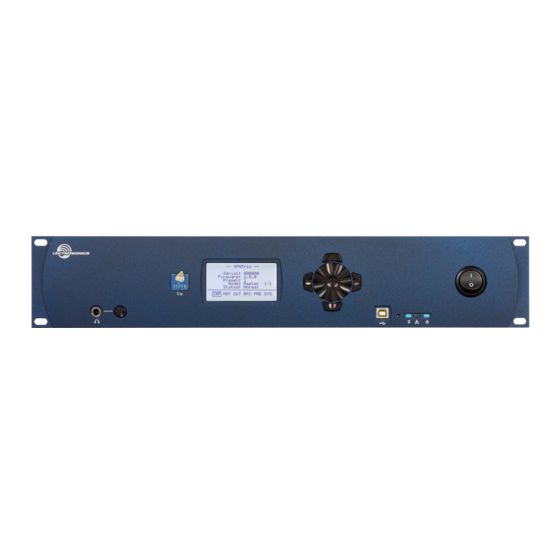
Page 5: Front Panel
Installation and Startup Guide Front Panel The SPNTrio includes a front panel LCD and rotary Blue LEDs on the right side of the front panel indicate style navigation control for adjustment without the need power status and communications through USB, serial for a computer interface. -
Page 6: Rear Panel
Power Amp Outputs The amplifier is designed to run continuously (idle or with a load) without heat buildup, making it ideal for permanent installations where prolonged operation is required. LECTROSONICS, INC. -
Page 7: Hardware Installation
Installation and Startup Guide Hardware Installation Installing the chassis into a rack Audio Inputs – Unbalanced Install the chassis so that the cooling fan vent is not Unbalanced audio sources include items such as consumer VCR’s, DVD players, etc., which can be con- blocked. -
Page 8: Audio Outputs
+5 V DC pins on the programmable input connector, as configuration allows the long as the maximum combined current for all LEDS two channels to be wired and relay coils does not exceed 100 mA. in parallel on a common load to double the output power. LECTROSONICS, INC. -
Page 9: Aspen Rs-232 Port
Installation and Startup Guide Cabling Of Stacked Units LED is ON when the programmable output is active +5VDC In a stacked configuration, ASPEN processors must 380 Ohms be interconnected as shown here. Each Slave unit in a stack gathers data and audio signals from the unit Pro gr amma b le Output Pi n below it, adds its own signals and passes the total on to the unit above it. -
Page 10: Creating An Aspen Installation Disk
ASPEN Installation Disk .iso file. http://www.lectrosonics.com/aspensupport/ Link from the home page: www.lectrosonics.com Save the file to your local drive in a familiar location. Open a disk copier utility such as Roxio Classic and select the operation to Burn from a Disk Image File. -
Page 11: Usb Driver Installation
Installation and Startup Guide USB Driver Installation The ASPEN USB drivers are installed from the ASPEN Installation Disk which comes with each device, by run- ning the ASPEN Device Installer. Normally this is done before connecting an ASPEN device to the PC for the first time, but it can be done afterwards if necessary. -
Page 12: Software Installation
Click on Next to confirm the installation and continue. The End User License Agreement screen appears. When the installation is complete the final screen will appear. Click on Close to finish the installation. Click on I Agree, then on Next to continue. LECTROSONICS, INC. -
Page 13: Software And Firmware Updates
Browse button http://www.gnarlywireless.com/AspenSupport/ Link on home page: http://www.lectrosonics.com ASPEN Software: Uninstall any previous version be- fore installing an updated version. 6) Do not disturb the USB cable connection during the Downloaded files arrive in a .zip format. Extract the files update process. -
Page 14: Connecting To A Unit
Scroll to additional tabs Click on the desired unit in the list Device settings tab Secondary setup tabs Scroll to additional tabs NOTE: Right click in the setup area for a Quick Select pull down list of available setup tabs LECTROSONICS, INC. -
Page 15: Minimum Setup Requirements
• Adjust gain on inputs in use Requirements • Invert polarity (phase) if needed • Select Mute/Unmute Since the SPNTrio contains an 8x12 mixer and a conference interface, setup is similar to configuring Adjust Gain using two separate processors. The following settings are... - Page 16 Mix Bus 47 is used the built-in amplifier in the SPNTrio. The power to create these mixes to keep them visually well amp outputs could just as well be used to power separated from the buses used for the Local Mixes.
- Page 17 Installation and Startup Guide Send Mixes: Each far end signal is routed to the Output Source tab opposite far ends, but not back to itself (mix-minus). AEC output: Contains the local microphone signals after the echo cancellation is applied, which is sent to the far ends along with the far end signals.
- Page 18 Navigate to each Output tab at the lower part of the Codec 1, Codec 2 and configure screen and adjust levels as needed. the interfaces as needed Outputs tab Scroll tabs Select tabs to access level setup screens for all outputs in use LECTROSONICS, INC.
-
Page 19: Saving Settings
Installation and Startup Guide Saving Settings Stacking Multiple Units If Slave units are not powered up when the Master unit Saving to a Preset boots up, the Slave may not be detected for several minutes. It is good practice to turn all units on simul- Settings must be saved to a preset in the processor to taneously or turn on Slave units before turning on the be available for normal operation. -
Page 20: Using The Lcd
The passcode can consist of any combination of five successive button presses of the four outer switches and the center switch such as: LEFT > RIGHT > UP > DOWN > CENTER. LECTROSONICS, INC. - Page 21 Installation and Startup Guide EXAMPLE: Mic/Line Input Setup accesses a setup After selecting the mode and/or changing the passcode, select SAVE with the rotary control and press the center screen where gain values, phantom power and polarity switch to save the settings. (phase) can be adjusted.
- Page 22 Output Setup accesses a setup screen to enter gain values and states for each output. Navigate to the desired output, select it and adjust the value with the rotary control. Press the control inward to Preset Recall and Settings store the setting. Rear Panel Controls LECTROSONICS, INC.
- Page 23 Installation and Startup Guide Select [PRE] in the Main Window to access a setup menu to store and recall presets and other options to define preset activities. It is useful for information, how- ever, it is recommended that you use the software GUI instead, which will provide access to presets stored on the computer disk drive.
-
Page 24: Browser Interface
IP address. The ad- dress will appear in the LCD. IP address will appear here. Enter Commands here View Replies here NOTE: ASPEN Commands are listed and explained in detail in the Help files included in the control panel software. LECTROSONICS, INC. -
Page 25: Multi-Site Bridging Setup
1, 2, 3, etc. for these mixes to keep them well separated in the matrix from the mixes used for confer- ence connections. There is no technical or performance reason for this separation; it simply makes it easier to visualize the matrix during setup. SPNTrio Processor Matrix Tab... -
Page 26: Aec Signal Mix
Codec 2 In Mixer Board Enable the AEC and define the busses Select the Acoustic Echo for the Signal and Reference mixes Canceller tab Signal added to mix (matrix) Mixes for output signals (outsource) AEC Reference Mix SPNTrio Processor Matrix Tab... -
Page 27: Send Mixes
Special Section - Multi-site Bridging SEND Mixes Assign the AEC output to the SEND mixes for the far side Assign the output of the AEC plus any multi-media sources to the mixes used to SEND audio to the far sides. The far side Codec and Telephone signals are routed in a mix-minus fashion so that each of them is sent to the outputs feeding the other two, but not back to itself:... -
Page 28: Local Mixes
Special Section - Multi-site Bridging LOCAL Mixes TEL and CODEC far end signals are routed to busses feeding the local sound system These mixes deliver the audio from the far sides and the microphones into the room. Signal routing for local sound reinforcement often uses a mix-minus configura- tion to reduce feedback in the local sound system and echo heard at the far side. -
Page 29: The Finished Setup
Special Section - Multi-site Bridging The Finished Setup In this example, crosspoints 1-1, 2-2 and 3-3 are set to the Phantom Mix mode. This allows the audio from that The setup for a multi-site conference was broken down input to participate in the automatic mixing algorithm, into separate steps on the previous pages. - Page 30 SPN Trio LECTROSONICS, INC.
-
Page 31: Fcc Part 68 Compliance
If trouble is experienced with this equipment, please This equipment uses the following USOC jacks: RJ11C. contact Lectrosonics, Inc. at (800) 821-1121 for repair The REN is used to determine the quantity of devices and/or warranty information. If the trouble is causing which may be connected to the telephone line. - Page 32 SPN Trio LECTROSONICS, INC.
-
Page 33: Service And Repair
There are no adjustments inside that will make a malfunctioning unit start working. LECTROSONICS’ Service Department is equipped and staffed to quickly repair your equipment. In warranty repairs are made at no charge in accordance with the terms of the warranty. Out-of-warranty repairs are charged at a modest flat rate plus parts and shipping. - Page 34 SPN Trio LECTROSONICS, INC.
- Page 35 Installation and Startup Guide Rio Rancho, NM...
- Page 36 This warranty does not apply to used or demonstrator equipment. Should any defect develop, Lectrosonics, Inc. will, at our option, repair or replace any defective parts without charge for either parts or labor. If Lectrosonics, Inc. cannot correct the defect in your equipment, it will be replaced at no charge with a similar new item.
Need help?
Do you have a question about the SPNTrio and is the answer not in the manual?
Questions and answers