Table of Contents

Subscribe to Our Youtube Channel
Related Manuals for Winmate R15L600-65EX


Summary of Contents for Winmate R15L600-65EX
- Page 1 15” IP65 Stainless ATEX Display Class I Division 2 R15L600-65EX User Manual Document Version 1.3 Document Part No. 9152150I100A Please read these instructions carefully before using this product, and save this manual for future use.
-
Page 3: Table Of Contents
15" ATEX Displays User Manual Contents Preface ............................2 Chapter 1: Introduction ......................... 7 1.1 Overview ......................... 8 1.2 Product Features ......................8 1.3 Packing List ........................8 1.4 Mechanical Dimensions ....................9 1.5 Physical Buttons and LED Indicators ................10 1.6 Hazardous Locations ..................... -
Page 4: Preface
15" ATEX Displays User Manual Preface Copyright Notice No part of this document may be reproduced, copied, translated, or transmitted in any form or by any means, electronic or mechanical, for any purpose, without the prior written permission of the original manufacturer. - Page 5 Preface Advisory Conventions Four types of advisories are used throughout the user manual to provide helpful information or to alert you to the potential for hardware damage or personal injury. These are Notes, Important, Cautions, and Warnings. The following is an example of each type of advisory. NOTE: A note is used to emphasize helpful information IMPORTANT:...
- Page 6 15" ATEX Displays User Manual Safety Precautions For your safety carefully read all the safety instructions before using the device. All cautions and warnings on the equipment should be noted. Keep this user manual for future reference. CAUTION / ATTENTION Do not cover the openings! Ne pas couvrir les ouvertures! *Let service personnel to check the equipment in case any of the following...
- Page 7 Preface Important Information Federal Communications Commission Radio Frequency Interface Statement This device complies with part 15 FCC rules. Operation is subject to the following two conditions: This device may not cause harmful interference. ⚫ This device must accept any interference received including interference ⚫...
- Page 8 2004/108/EC; Independent 3rd party assessment (Accredited by IEC 17025) About This User Manual This User Manual provides information about using the Winmate® 15-inch IP65 Stainless ATEX Display, which includes a detailed description of how to use the display, its components, and features.
-
Page 9: Chapter 1: Introduction
15" ATEX Displays User Manual Chapter 1: Introduction This chapter gives you product overview, describes features and hardware specification. You will find all accessories that come with the device in the packing list. Mechanical dimensions and drawings included in this chapter. -
Page 10: Overview
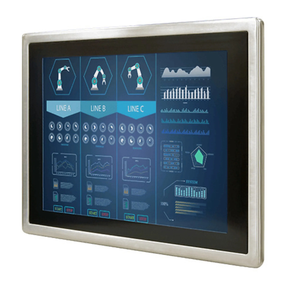
15" ATEX Displays User Manual 1.1 Overview 15-inch Stainless ATEX Display has a footprint of 15.6 x 12.2 inches and is less than two inches thick. The sturdy stainless-steel housing has anti-corrosion protection and carries an IP65/NEMA4 sealing rating, meaning that it's completely protected against dust, and also protected against low pressure water jets from all directions. -
Page 11: Mechanical Dimensions
Chapter 1: Introduction User’s Manual Touch Driver CD 1.4 Mechanical Dimensions Unit: mm... -
Page 12: Physical Buttons And Led Indicators
15" ATEX Displays User Manual 1.5 Physical Buttons and LED Indicators Physical buttons and LED indicators located on the rear side of the Display. Physical Buttons Icon Button Description Down/ Volume Press to decrease the volume or volume down when Down without OSD menu. -
Page 13: Hazardous Locations
Chapter 1: Introduction 1.6 Hazardous Locations This equipment (R15L600-65EX) is primarily intended for use in Class I, Division 2 Groups A, B, C, and D; or non-hazardous locations only. It is suitable for use in oil, gas, and petrochemical manufacturing plants and locations where ignitable gases or vapor may be presented. This device is typically used for automation or control purposes. -
Page 14: Chapter 2: Getting Started
15" ATEX Displays User Manual Chapter 2: Getting Started This chapter provides information on how to connect the device to the source of power, connector pinouts, OSD menu navigation, and the guideline to turn on/off the Display. -
Page 15: Turning On And Off Your Device
Chapter 2: Getting Started 2.1 Turning On and Off Your Device IMPORTANT: Power button is located under the enclosure on the rear side of the Display. In order to access it, you need to open the enclosure. 1. Remove the protective cap out of the DC IN Jack. 2. -
Page 16: Osd Menu Navigation
15" ATEX Displays User Manual 2.2 OSD Menu Navigation GAMMA0 BRIGHTNESS BRICONTRAST GAMMA GAMMA1 CONTRAST GAMMA2 Only support VGA POSITION CHANNEL ANALOG mode Only support VGA IMAGE RECALL mode USER 9300K COLOR OSD EXIT 6500K ADC RIGHTNESS VOLUME ADJUST OPTION SPEAK ON/OFF BRICONTRAST OSD icon... - Page 17 Chapter 2: Getting Started COLOR OSD icon Sub menu Settings Note USER R.G.B slider bar Choose RED/GREEN/BLUE to set value of color temperature brightness to suit you own preference 9300K Select and execute Use to set value of monitor for the CIE coordinate 9300 color temperature COLOR 6500K Select and execute...
- Page 18 15" ATEX Displays User Manual EXIT OSD icon Sub menu Settings Note Select and execute Exit the OSD menu Select and execute EXIT Return to main menu...
-
Page 19: Connectors
Chapter 2: Getting Started 2.3 Connectors 2.3.1 Wiring Requirements The following common safety precautions should be observed before installing any electronic device: • Strive to use separate, non-intersecting paths to route power and networking wires. If power wiring and device wiring paths must cross make sure the wires are perpendicular at the intersection point. -
Page 20: Atex Zone 2 Workstation
15" ATEX Displays User Manual 2.3.2 ATEX Zone 2 Workstation The connector cables are located under the enclosure (optional accessory). You need to connect wires first (refer to Chapter 1.4 to find the connector placement), install the pipe, insert the wires into the pipe opening, and then secure the cover box to the Display. -
Page 21: Connector Pinouts
Chapter 2: Getting Started 2.3.3 Connector Pinouts This Display is equipped with four connectors which are IP65 level and fool-proofing design. Use only the cables that are included in the package. The pin assignments of the cables are as follows: IMPORTANT: Minimum input cables size is 18AWG, Minimum temperature rating of the cables is 105°C. - Page 22 15" ATEX Displays User Manual 2.3.3.3 RS-232 Cable (For Remote Control) 2.3.3.4 Power Adapter NOTE: The adapter is certified by UL, CUL TUV/GS CE, FCC, BSMI, EK, DOIR+C-TICK, CCC, PSE.
- Page 23 Chapter 2: Getting Started 2.3.3.5 DC Power Cable (Open Wire) WARNING! / AVERTISSEMENT! Ensure that the external power source is OFF before connecting or disconnecting the DC IN jack. Assurez-vous que la source d'alimentation externe est coupée avant de brancher et de débrancher la prise DC IN.
-
Page 24: Chapter 3: Installation
15" ATEX Displays User Manual Chapter 3: Installation This chapter provides mounting guide for all available mounting options and hardware installation instructions. Pay attention to cautions and warning to avoid any damages. -
Page 25: Cable Mounting Considerations
Chapter 3: Installation 3.1 Cable Mounting Considerations For a nice look and safe installation, make sure cables are neatly hidden behind the Display. Refer to Chapter 2.3 for the cable installation instruction. CAUTION / ATTENTION Follow mounting instructions and use recommended mounting hardware to avoid the risk of injury. -
Page 26: Vesa Mount
15" ATEX Displays User Manual 3.3.1 VESA Mount 3.3.1.1 Wall Mount Standalone Stainless Display comes with VESA Mount solution. Follow the instruction below to complete mounting. Tools needed: Size Where used Quantity Appearance Screw M3x 6 Secure the metal plate to the bottom side Secure the box cover on the top side... - Page 27 Chapter 3: Installation Mounting Steps: Step 1 First, you need to open the enclosure (box cover) to install VESA Plate to the enclosure of the Display. *with customer’s bracket Exploded drawing: Item No. Description Top cover lid of the enclosure Bottom cover plate of the enclosure The conduit...
- Page 28 15" ATEX Displays User Manual To open the enclosure, follow the steps below: Description Picture 1. Turn the Display face down. 2. Loosen screws (M4 x 6) on two metal plates that secure enclosure to the Display from each side. 3.
- Page 29 Chapter 3: Installation To install VESA Plate, follow the steps below: Description Picture 1. Fasten four Philips M5x10 flathead screws from the inside of the box top cover. 2. Secure the VESA plate from the outside with four metal nuts.
- Page 30 15" ATEX Displays User Manual Step 3 Align all the wires and insert into the pipe opening (refer to Chapter 2.3 for pipe installation instructions). Step 4 Secure the cover box on both top (three screws) and bottom (four screws) sides with M3 x 6 Philips flathead screws, and fasten the screws (M3 x 6) that secure box cover on the left and right sides;...
-
Page 31: Panel Mount
Tools required: • 15 x M3 truss head screws, length 15 mm or 8 mm. • Waterproof rubber. • Screwdriver (not supplied by Winmate). NOTE: Choose screw length based on the thickness of your fixture. - Page 32 15" ATEX Displays User Manual Installation instruction: 1. Make a cutout on the fixture (e.g., wall) 2. Place the Display and a waterproof rubber according to the cutout dimension of the on the fixture from the front side. The sides Display.
-
Page 33: Chapter 4: Maintenance
Chapter 4: Maintenance Chapter 4: Maintenance This chapter provides information on regular cleaning and maintenance procedures. Follow all the recommendations included in this chapter in order to ensure long product lifecycle. -
Page 34: Cleaning The Display Screen
15" ATEX Displays User Manual 4.1 Cleaning the Display Screen • Wipe the screen with a clean, soft, lint-free cloth. This removes dust and other particles. Do not use acetone, ethyl alcohol, toluene, ethyl acid or methyl chloride to clear the panel. It may permanently damage the display screen. -
Page 35: Appendix
Appendix Appendix Appendix A: Product Specifications Model Name R15L600-65EX Item Specifications Display: Panel Size 15-inch Resolution 1024 x 768 550 nits Brightness 1000 nits (Optional) Contrast Ratio 2000:1 (typ.) View Angles 88,88,88,88 Touch Resistive touch screen bonding with panel (explosion-proof) Display Color 16.2M Colors... - Page 36 M12 Type RS232 Male Cable for touch screen control (Optional) NOTE Accessories and Integrated Options may vary depending on your configuration. The product shown in this user manual is a standard model. For diagrams that contain customized or optional I/O, please contact the Winmate Sales Team for more information.
-
Page 37: Appendix B: Remote Control Set Command
Appendix Appendix B: Remote Control Set Command Function Length Command index Value Checksum(*1) 1 Power 0x05 0x40 0x00 0= ON/OFF 0xBB= ON/OFF 2 Auto 0x05 0x40 0x01 0=Auto 0xBA=Auto 3 Recall 0x05 0x40 0x02 0=Recall 0xB9=Recall 4 White Balance 0x05 0x40 0x03 0=White Balance 0xB8=White Balance... - Page 38 Winmate Inc. 9F, No.111-6, Shing-De Rd., San-Chung District, New Taipei City 24158, Taiwan, R.O.C www.winmate.com Copyright © 2022 Winmate Inc. All rights reserved.
Need help?
Do you have a question about the R15L600-65EX and is the answer not in the manual?
Questions and answers