
Related Manuals for Johnson Controls DOA096B21S Series


Summary of Contents for Johnson Controls DOA096B21S Series
- Page 1 ENGINEERING MANUAL INVERTER-DRIVEN MULTI-SPLIT SYSTEM HEAT PUMP AIR CONDITIONERS Technical Catalog for Outdoor Unit Engineering Manual < Indoor Units > ● DOAS (Dedicated Outdoor Air System) Type (H,Y)DOA096B21S TC-16005...
-
Page 3: Important Notice And Safety Summary
Never bypass or jump-out any safety device or switch. ● Johnson Controls will not assume any liability for injuries or damage caused by not following steps outlined or described in this manual. Unauthorized modifications to Johnson Controls products are prohibited as they…... - Page 4 Take the following precautions to reduce the risk of property damage. ● Be careful that moisture, dust, or variant refrigerant compounds not enter the refrigerant cycle during installation work. Foreign matter could damage internal components or cause blockages. ● If air filters are required on this unit, do not operate the unit without the air filter set in place. If the air filter is not installed, dust may accumulate and breakdown may result.
-
Page 5: Installation Precautions
Installation Precautions To reduce the risk of serious injury or death, the following installation precautions must be followed. ● When installing the unit into… ◦ A wall: Make sure the wall is strong enough to hold the unit’s weight. It may be necessary to construct a strong wood or metal frame to provide added support. -
Page 6: Refrigerant Precautions
Controls uses only refrigerants that have been approved for use in the unit’s intended home country or market. Johnson Controls distributors similarly are only authorized to provide refrigerants that have been approved for use in the countries or markets they serve. The refrigerant used in this unit is identified on the unit’s faceplate and/or in the associated manuals. - Page 7 When shielded cabling is applied, proper bonding and termination of the cable shield is required as per Johnson Controls guidelines. Plenum and riser ratings for communication cables must be considered per application and local code requirements.
-
Page 8: Table Of Contents
- CONTENTS - IMPORTANT NOTICE AND SAFETY SUMMARY ..................i 1. Introduction ..............................i 2. Important Safety Instructions ........................i 1. General Information (Features) ........................1-1 2. DOAS (Dedicated Outdoor Air System) Type .................... 2-1 2.1 Unit Nomenclature ..........................2-1 2.2 Line-up .............................. -
Page 9: General Information (Features)
1. General Information (Features) VRF Air Conditioners Johnson Controls proudly introduces new Variable Refrigerant Flow (VRF) air conditioners, a highly-efficient and reliable air-conditioning system. Recently, increased numbers of buildings are requiring "Intelligent" facilities that include communication networks, office automation, and a comfortable environment. In particular, a comfortable environment is becoming more of a year-around requirement in office buildings. - Page 10 FEATURES < Outlet Air Temperature Control > In this mode, the control system bring the outlet temperature closer to the setting temperature of the wired controller, using an outlet air thermistor in the unit. [Advantage] When it is set introduce outdoor air, the system enable intake of fresh air without impacting the room temperature.
- Page 11 FEATURES ■ Operation Range Heating Operation Cooling Operation Available Range Operation Available Range 19.4 109.4 (-7) (-5) (10) (15) (20) (25) (30) (35) (40) (43) Outdoor Air Intake Temperature [ F DB ( C DB)] NOTES: 1. The above figure shows the sensed temperature of inlet air thermistor for the DOAS unit. 2.
-
Page 13: Doas (Dedicated Outdoor Air System) Type
DOAS 2. DOAS (Dedicated Outdoor Air System) Type 2.1 Unit Nomenclature Model Descriptions Example Nomenclature Description H = Hitachi Brand Y = York Brand DOA = Dedicated Outdoor Air System Capacity (MBH) Refrigerant Type B = R410A Voltage 2 = 208/230Volts - 1Phase - 60Hz 1 = 1st Generation S = Standard Type 2.2 Line-up... -
Page 14: General Data
DOAS 2.3 General Data DOAS Indoor Unit Type Model (H,Y)DOA096B21S AC 1Phase, 208/230V, 60Hz Indoor Unit Power Supply Outlet Air Temperature Control *1 96,000 Nominal Cooling Capacity Btu/h (28.2) (kW) 60,000 Nominal Heating Capacity Btu/h (17.6) (kW) Indoor Temperature Control *2 Nominal Cooling Capacity Btu/h 96,000... -
Page 15: Dimensional Data
DOAS 2.4 Dimensional Data Model: (H,Y)DOA096B21S (Produced in 2017 or earlier) Unit: inch (mm) TC-16005-rev.2... - Page 16 DOAS Model: (H,Y)DOA096B21S (Produced in 2018 or later) Unit: inch (mm) TC-16005-rev.2...
-
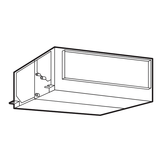
Page 17: Structure
DOAS 2.5 Structure Model: (H,Y)DOA096B21S Unit: inch (mm) 50 (1270) TC-16005-rev.2... -
Page 18: Component Data
DOAS 2.6 Component Data Indoor Heat Exchanger and Fan Model (H,Y)DOA096B21S Heat Exchanger Type Multi-Pass Cross Finned Tube Copper Tube Tube Material Outer Diameter 1/4 (7.0) in. (mm) Rows Number of Tube/Coil Material Aluminum Pitch in. (mm) 1/16 (1.6) Maximum Operating Pressure psi (MPa) 601 (4.15) Total Face Area... -
Page 19: Operation Space
DOAS 2.7 Operation Space Model: (H,Y)DOA096B21S Unit: inch [mm] Electrical Control Box Service Access Door (Min. 23-5/8 [600] 5-7/8 to 7-7/8 [150 to 200] Min. 23-5/8 Min. 31-1/2 [600] [800] If the ceiling board can not be detected for servicing, prepare a service access door below the indoor unit for removing the indoor unit. -
Page 20: Fan Performance
DOAS 2.8 Fan Performance TC-16005-rev.2... -
Page 21: Electrical Data
DOAS 2.9 Electrical Data Indoor Unit Main Power Applicable Voltage Power Supply Unit Fan Motor Model PH HZ Maximum Minimum 0.402 (H,Y)DOA096B21S 208/230 (Motor 2 pcs) VOL: Rated Unit Power Supply Voltage (V) Phase Frequency (Hz) MCA: Maximum Circuit Ampacity (A) MFA: Maximum Fuse Ampacity (A) OPT: Rated Motor Output (kW) FLA: Full Load Ampacity (A) -
Page 22: Sound Data
DOAS 2.10 Sound Data NOTES: 1. The sound pressure level is based on the following: Measurement Point: 4.9 ft. (1.5m) beneath the unit. 2. The above data is measured in an anechoic chamber therefor reflected sound should be taken into consideration in the field. -
Page 23: Control System
DOAS 2.11 Control System 2.11.1 Refrigerant System Model: (H,Y)DOA096B21S Mark Part Name Heat Exchanger Distributor Strainer Electronic Expansion Valve Unit: inch (mm) (A) Gas Pipe (B) Liquid Pipe Model Distributor (C) OD×T (D) OD×T Connection Connection f7/8 f3/8 f1×t0.063 f1/2×t0.039 (H,Y)DOA096B21S 9 Pass (22.2) -
Page 24: Operating Temperature Range
DOAS 2.11.2 Operating Temperature Range Cooling Blowing Heating 19.4 [-7] [10] [15] [20] [30] [33.5] [40] [43] Inlet Air Temp. Dry Bulb ( C] DB) (Outdoor Air Temp.) NOTES: 1. The above figure shows the sensed temperature of inlet air thermistor for the DOAS unit. 2. -
Page 25: Control Temperature
DOAS 2.11.3 Control Temperature < Indoor Temperature Control > Cooling Heating Set Point Temperature Range F (19 C) ~ 86 F (30 F (17 C) ~ 86 F (30 for Wired Controller [Inlet Temp.] > [Setting Temp.] +2 F (+1 [Inlet Temp.] <... -
Page 26: Standard Operation Sequence
DOAS 2.11.4 Standard Operation Sequence (1) Control Flowchart DOAS inlet air is outdoor air. As long as DOAS outdoor air inlet temperature does not reach the setting temperature of the controller, thermo-OFF is not available and the operation is continued. In addition, outdoor airflow directly into the indoor unit during thermo-OFF. - Page 27 DOAS (2) Freeze Protection Control DOAS operates the forced heating operation for freeze protection of the heat exchanger if the outdoor air inlet temperature is 32 F (0 C) or less during the cooling or airflow operation. However, the operation is stopped if the outdoor air inlet temperature is 19.4 F (-7 C) or less, or the temperature in the circuit is decreased.
-
Page 28: Safety And Control Device Setting
DOAS 2.11.5 Safety and Control Device Setting Model (H,Y)DOA096B21S For Evaporator Fan Motor Internal Thermostat Automatic Reset, Non-Adjustable 302+9 Cut-Out (150+5) 223+27 Cut-In (106+15) For Control Circuit Fuse Capacity 2-16 TC-16005-rev.2... -
Page 29: Wiring Diagram
DOAS 2.11.6 Wiring Diagram 2-17 TC-16005-rev.2... -
Page 31: Optional Parts
OPTIONAL PARTS 3. Optional Parts 3.1 Line Up Optional Parts Item No. Optional Parts Model Name Seismic Suspension Bracket SSB-IDH-01 Infrared (IR) Receiver Kit CWDIRK01 3P Connector Cable PCC-1A Remote Sensor THM-R2A Relay and 3 Pin Connector Kit PSC-5RA Wired Controller CIW01 Simplified Wired Controller CIS01... -
Page 32: Seismic Suspension Bracket: Ssb-Idh-01
OPTIONAL PARTS 3.2 Seismic Suspension Bracket: SSB-IDH-01 Replace the original suspension bracket to this seismic suspension bracket to prevent destruction or damage to the ducted indoor unit during earthquake by improving its strength. 3.2.1 Applicable Unit Model SSB-IDH-01 Required Qty. Applicable Indoor Unit (H,Y)IDH072, 096B21S, (H,Y)DOA096B21S 3.2.2... -
Page 33: Infrared (Ir) Receiver Kit: Cwdirk01
OPTIONAL PARTS 3.3 Infrared (IR) Receiver Kit: CWDIRK01 This IR receiver kit is installed with the wall mount to use with the wireless controller. 3.3.1 Specifications Model CWDIRK01 Outer Dimension 3-9/16 × 4-3/4 × 1-1/8 inch < W × H × D > (90 ×... -
Page 34: Accessories / Options
OPTIONAL PARTS 3.3.4 Accessories / Options Accessory Remarks IR Receiver Kit With Connecting Cable CWDIRK01 Cable Band For Clamping Cable Securing Screw For Installing IR Receiver Kit Securing Screw For Fixing Cable Clamp Cable Clamp For Clamping Cable 3.3.5 Installation ●... - Page 35 OPTIONAL PARTS Perform the installation work for the IR receiver kit while the indoor unit is being installed. Turn OFF the power supply for the indoor unit if the IR receiver kit is attached after the indoor unit is installed. Slot Install the IR receiver kit using the length of connecting cable (accessory).
- Page 36 OPTIONAL PARTS (2) Select the connecting cable outlet direction (2) Run the connecting cable into the metal and cut out one of the knock-out holes on conduit. the cover. The connecting cable should not be exposed. Lead it through the metal conduit in the wall. Select the connecting cable outlet direction and cut out of the...
-
Page 37: Electrical Wiring
OPTIONAL PARTS 3.3.6 Electrical Wiring The terminal block (TB2) for the controller cable is located as shown in the figure below. Connect the connecting cable for the IR receiver kit to terminals A and B at TB2. (There is no polarity between terminals A and B.) The details for wiring methods can be found in the “Installation and Maintenance Manual”... -
Page 38: Setting Dip Switch On Ir Receiver Kit Side
OPTIONAL PARTS 3.3.8 Setting DIP Switch on IR Receiver Kit Side Turn OFF the power supply completely before setting the DIP switch for an IR receiver kit. Not doing so may cause an electric shock. The following switches are on the IR receiver kit. NOTE: When the case is closed, pay particular attention to the outlet position for connecting cable. -
Page 39: Identifying Indoor Units Installed In A Side-By-Side Operation
OPTIONAL PARTS 3.3.9 Identifying Indoor Units Installed in a Side-by-Side Operation Turn OFF the power supply completely before setting the DIP switch for the IR receiver kit. Not doing so can cause an electric shock. When two indoor units are installed side by side, Indoor Unit Indoor Unit the commands from the wireless controller may... -
Page 40: Simultaneous Operation
OPTIONAL PARTS 3.3.10 Simultaneous Operation ● Turn OFF the power supply completely before setting the DIP switch and electrical wiring work for the IR receiver kit. Not doing so can cause an electric shock. ● Accurately perform the electrical wiring work. If the electrical work is not completed correctly, heat generation at the connection, a fire, or an electric shock may occur. - Page 41 OPTIONAL PARTS Electrical Wiring Connecting and Setting Connection between Indoor Units Perform the connection work as shown below. Power Supply Cable 208/230V Indoor Unit No.1 Indoor Unit No.2 Indoor Unit No.3 Power Supply A B 1 2 A B 1 2 A B 1 2 Cable (208/230V)
-
Page 42: Test Run By Wireless Controller (Cir01)
OPTIONAL PARTS 3.3.11 Test Run by Wireless Controller (CIR01) After all installations are completed, a test run should be performed. (1) Perform the test run according to the Installation Manual of the wireless controller. (2) The test run from the wireless controller switch takes two hours to complete. NOTE: For the wall mount indoor units, if the TIMER indicator (green) is flashing (0.5 second ON/0.5 second OFF) after two hours, an alarm may occur. -
Page 43: Connector Cable: Pcc-1A
OPTIONAL PARTS 3.4 3P Connector Cable: PCC-1A This accessory connector is utilized to provide remote start/stop capability (binary input) to an indoor unit and provide operating status (binary output) of an indoor unit's functions. (System Parts: One set contains five 3P cords.) Connector (“XARP-03V”... -
Page 44: Relay And 3 Pin Connector Kit: Psc-5Ra
OPTIONAL PARTS 3.6 Relay and 3 Pin Connector Kit: PSC-5RA This relay kit provides for basic input/output integration functionality (indoor unit ON/OFF, operating mode, alarm status) to third party controllers and Building Management Systems (BMS). Unit: inch (mm) Max. 4-1/2 (115) 4 (101) 5/16 5/16... -
Page 45: Selection Data
SELECTION DATA 4. Selection Data 4.1 Selection Guide (1) Key for Terms Used for DOAS Units Nomenclature Description H = Hitachi Brand Y = York Brand DOA = Dedicated Outdoor Air System Capacity (MBH) Refrigerant Type B = R410A Voltage 2 = 208/230Volts - 1Phase - 60Hz 1 = 1st Generation S = Standard Type... - Page 46 SELECTION DATA (3) Combination of Outdoor Unit and DOAS Unit Indoor units can be connected to the outdoor unit (VRF system). Refer to the table below for connection capacity ratio of each outdoor unit. < Connection Capacity Ratio > DOAS with other Indoor Units DOAS Only [ Capacity of DOAS shall be Outdoor Unit Model Name...
-
Page 47: Capacity Table
SELECTION DATA 4.2 Capacity Table 4.2.1 Cooling Capacity Outdoor Air Temp. F WB) Outdoor Air (MBH) (MBH) (MBH) (MBH) (MBH) (MBH) (MBH) (MBH) Temp. ( F DB) 32.3 34.7 32.3 34.6 32.3 34.4 36.4 32.3 34.2 37.1 49.6 34.1 37.8 49.6 72.4 33.9... - Page 48 © 2016 Johnson Controls, Inc. TC-16005-rev.2 Code No. LIT-12012282 Revised April 2018...
Need help?
Do you have a question about the DOA096B21S Series and is the answer not in the manual?
Questions and answers