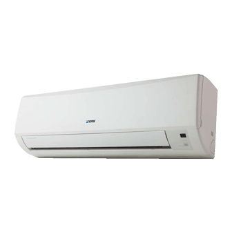
Johnson Controls P Series Installation And Maintenance Manual
9k - 12k - 115v inverter-driven air conditioning units
Hide thumbs
Also See for P Series:
- Installation and maintenance manual (50 pages) ,
- Installation and maintenance manual (44 pages)
Table of Contents
Advertisement
Quick Links
- 1 Table of Contents
- 2 Installation Dimension Diagram
- 3 Electric Connection Requirement
- 4 Installation of Indoor Unit
- 5 Installation - Checking Parts
- 6 Error Code List
- 7 Troubleshooting Procedures
- 8 Customer Service, Technical Support
- Download this manual
See also:
Installation and Maintenance Manual
Installation and
Maintenance
Manual
"P" SERIES
9K - 12K - 115V
INVERTER-DRIVEN AIR
CONDITIONING UNITS
Type
INDOOR UNITS
Type
DCP09CSB11S
DHP09CSB11S
OUTDOOR UNITS
DCP12CSB11S
DHP12CSB11S
PLEASE READ AND
UNDERSTAND THIS
MANUAL BEFORE USING
THIS INVERTER-DRIVEN
AIR CONDITIONING UNIT.
KEEP THIS MANUAL FOR
FUTURE REFERENCE.
Model
DCP09NWB11S
DHP09NWB11S
DCP12NWB11S
DHP12NWB11S
Model
Advertisement
Table of Contents
Troubleshooting

Subscribe to Our Youtube Channel
Related Manuals for Johnson Controls P Series


Summary of Contents for Johnson Controls P Series
- Page 1 Installation and Maintenance Manual "P" SERIES 9K - 12K - 115V INVERTER-DRIVEN AIR CONDITIONING UNITS Type Model DCP09NWB11S DHP09NWB11S INDOOR UNITS DCP12NWB11S DHP12NWB11S Model Type DCP09CSB11S DHP09CSB11S OUTDOOR UNITS DCP12CSB11S DHP12CSB11S PLEASE READ AND UNDERSTAND THIS MANUAL BEFORE USING THIS INVERTER-DRIVEN AIR CONDITIONING UNIT.
- Page 2 Important Notice ● Johnson Controls, Inc. pursues a policy of continuing improvement in design and performance in its products. As such, Johnson Controls, Inc. reserves the right to make changes at any time without prior notice. ● Johnson Controls, Inc. cannot anticipate every possible circumstance that might involve a potential hazard.
-
Page 3: Table Of Contents
Table of Contents ...........i 2. Installation ........................ . 2.1 Installation Dimension Diagram ..................1 ............... 2. Installation Procedures ....................3 2.4 Installation - Checking Parts ...................4 2.5 Selection of Installation Location ..................4 2.6 Electric Connection Requirement ..................4 2.7 Installation of Indoor Unit ....................4 2.8 Installation of Outdoor Unit ....................6 2.9 Vacuum Pump/Leak Detection ..................8 2.10 Post Installation Testing....................8... - Page 4 Never bypass or jump-out any safety device or switch. ● Johnson Controls, Inc. will not assume any liability for injuries or damage caused by not following steps outlined or described in this manual. Unauthorized modifications to Johnson Controls products are prohibited as they…...
- Page 5 Take the following precautions to reduce the risk of property damage. ● Be careful that moisture, dust, or variant refrigerant compounds not enter the refrigerant cycle during installation work. Foreign matter could damage internal components or cause blockages. ● If air filters are required on this unit, do not operate the unit without the air filter set in place. If the air filter is not installed, dust may accumulate and breakdown may result.
- Page 6 Controls uses only refrigerants that have been approved for use in the unit’s intended home country or market. Johnson Controls distributors similarly are only authorized to provide refrigerants that have been approved for use in the countries or markets they serve. The refrigerant used in this unit is identified on the unit’s faceplate and/or in the associated manuals.
- Page 7 under pressure and never open pressurized system parts. ● Before installation is complete, make sure that the refrigerant leak test has been performed. If refrigerant gases escape into the air, turn OFF the main switch, extinguish any open flames and contact your service contractor.
- Page 8 ● Communication cabling shall be a minimum of 18-Gauge, 2-Conductor, Stranded Copper. Shielded cable must be considered for applications and routing in areas of high EMI and other sources of potentially excessive electrical noise to reduce the potential for communication errors. When shielded cabling is applied, proper bonding and termination of the cable shield is required as per Johnson Controls guidelines.
-
Page 9: Installation Dimension Diagram
2. Installation 2.1 Installation Dimension Diagram Space to the wall Space to the wall At least 5 7/8 inch At least 5 7/8 inch Condensate pipe Installation and Maintenance... - Page 10 2.2 Main Tools for Installation and Maintenance 1. Level meter, measuring tape 2. Screw driver 3. Impact drill, drill head, electric drill 4. Electroprobe 5. Universal meter 6. Torque wrench, open-end wrench, inner hex wrench 9. Manifold gauge 7. Electronic leakage detector 8.
-
Page 11: Installation Procedures
2.3 Installation Procedures Start installation Preparation before installation Select installation Read the requirements Prepare tools for electric connection location Select indoor unit Select outdoor unit installation location installation location Install outdoor unit mount Install wall-mounting frame, drill wall holes (select it according to the actual situation) Connect pipes of indoor IMount outdoor unit unit and condendsate pipe... -
Page 12: Installation - Checking Parts
2.4 Installation - Checking Parts 2.6 Electric Connection Requirement Name Name Sealant 1. Safety Precaution (1) All electric safety regulations must be followed when Wrapping tape installing the unit. Connection pipe (2) Use proper power supply circuit and air switch in Condensate pipe accordance with local safety regulations. - Page 13 5. Connect the Pipe of Indoor Unit s are page 3. Install Wall-mounting Frame Wall Wall Level meter Mark in the middle of it Space Space Open-end to the to the wrench wall wall above above Union nut 150mm 150mm Pipe Pipe joint Union nut...
-
Page 14: Installation Of Outdoor Unit
7. Connect Wire of Indoor Unit 8. Bind up Pipe Screw Panel Wiring cover Indoor and outdoor power cord Indoor unit pipe Liquid pipe Band Condensate hose Condensate hose Connection pipe Band connection wire sleeve Indoor power cord Note: winding. condensate 9. - Page 15 Note: 5. Connect Outdoor Electric Wire The outdoor unit should be installed above the snow line screws are needed. cable cross plate sub-assy N(1) 2 green white black white green (yellow- (blue) black (brown) (brown) (blue) (yellow- green) green) Indoor unit connection POWER Drain vent Chassis...
-
Page 16: Vacuum Pump/Leak Detection
2. Leakage Detection Note: condensate 2.10 Post Installation Testing 1. Check after Installation The condensate hose can't be fluctuant installation. The water outlet can't be placed The condensate hose in water can't be fluctuant The water outlet can't be emit noise. fluctuant water dripping. -
Page 17: Maintenance
3. Maintenance 3.1 Precautions before Maintenance There are high-capacity electrolytic capacitors on the outdoor mainboard. Thus, even if the power is cut off, there is high voltage inside the capacitors and it needs more than 20 min. to reduce the voltage to safety value. Touching the electrolytic capacitor within 20 min. after cutting the power will cause electric shock. -
Page 18: Error Code List
3.2 Error Code List Display of lamp (the times of blinking) Display of Name of malfunction Indoor Outdoor indoor unit Anti-freezing protection Block or Low pressure of refrigerant system Compressor exhaust high temperature protection AC over-current protection Communication failure between indoor unit and outdoor unit Anti-high temperature protection No feedback of indoor fan motor Jumper cap malfunction protection... -
Page 19: Troubleshooting Procedures
3.3 Troubleshooting Procedures Indoor unit (1) Malfunction of Temperature Sensor F1, F2 Main detection points: Start eliminated eliminated eliminated Installation and Maintenance... - Page 20 (2) Malfunction of Blocked Protection of IDU Fan Motor H6 Main detection points: Start eliminated eliminated and motor correctly eliminated control terminal for PG motor is Replace PG motor eliminated Installation and Maintenance...
- Page 21 (3) Malfunction of Protection of Jumper Cap C5 Main detection points: Start eliminated eliminated eliminated Installation and Maintenance...
- Page 22 (4) Malfunction of Zero-crossing Inspection Circuit Malfunction of the IDU Fan Motor U8 Main detection points: Start U8 is still displayed Installation and Maintenance...
- Page 23 4. Communication malfunction E6 Start Cut off power supply. Check if connection line of IDU and ODU and the wire inside electric box are correctly connected. Connect the line Correct connection? according to Malfunction eliminated? wiring diagram. Main board matches Match correctly with display board? Main board of Malfunction eliminated?
- Page 24 Outdoor unit: (1) Capacitor charge fault (Fault with outdoor unit) (AP1 below refers to the outdoor control panel) Turn on the unit and wait 1 minute Use DC voltmeter to measure the voltage on the two ends of electrolytic capacitor Fault with the voltage Replace the control testing circuit on...
- Page 25 (2) IPM Protection, Out-of-step Fault, Compressor Phase Overcurrent (AP1 below refers to the outdoor control panel) Installation and Maintenance...
- Page 26 Energize and switch on Use AC voltmeter If the voltage Check the supply to measure the IPM protection between terminal L voltage and voltage between occurs after the and N on wiring machine has run for terminal L and N restore it to board XT is within a period of time?
- Page 27 (3) High temperature and overload protection diagnosis (AP1 hereinafter refers to the control board of the outdoor unit) Mainly detect: Overheat and high temperature protection Normal protection, please operate it after the outdoor ambient temp- Is outdoor ambient temperature higher than 53? erature is normalized.
- Page 28 (4) Start-up failure (following AP1 for outdoor unit control board) Mainly detect: Power on the unit Restart it up after Is stop time of the compressor 3 minutes longer than 3 minutes? Does startup fail? Connect the wires as Are the wires for the compressor connected per the connection correctly? Is connection sequence right? diagram...
- Page 29 Service Manual (5) Out of step diagnosis for the compressor (AP1 hereinafter refers to the control board of the outdoor unit) Mainly detect: Out of step occurs in Out of step occurs once the operation unit is powered on. Check if the fan terminal Is stop time of the Replace the fan Is the outdoor fan working...
- Page 30 (6) Overload and air exhaust malfunction diagnosis (following AP1 for outdoor unit control board) Mainly detect: 20 minutes after the complete unit is powered off Is the terminal FA for the Connect the electronic expansion valve wires correctly connected correctly? Resistances between the first four pins close to the terminal hole and the fifth pin are almost the same, less than 100...
- Page 31 (7) Power factor correct or (PFC) fault (a fault of outdoor unit) (AP1 hereinafter refers to the control board of the outdoor unit) Mainly detect: Start Check wiring of the reactor (L) of the outdoor unit and the PFC capacitor Replace it as per the Whether there is any wiring diagram and...
- Page 32 (8) Communication malfunction: (following AP1 for outdoor unit control board) Mainly detect: Start Did the equipment operate normally before the failure occurs? Check the wiring of the indoor and outdoor units with reference to the wiring diagram Check wiring inside of the indoor and outdoor Is the connection right? units...
- Page 33 (9) Malfunction of Overcurrent Protection Main detection points: Start eliminated eliminated eliminated eliminated model eliminated eliminated opened completely) eliminated Installation and Maintenance...
-
Page 34: Troubleshooting For Normal Malfunction
3.4 Troubleshooting for Normal Malfunction 1. Air Conditioning Unit Doesn't Start connected well. Wrong wire connection between or poor connection for wiring terminals reliably correctly once improper Replace batteries for remote controller Repair or replace remote controller 2. Poor Cooling (Heating) for Air Conditioning Unit Small wind blow motor is set too low conditioner... - Page 35 4. ODU Fan Motor Doesn't Operate Connect wires according to wiring diagram to Wrong wire connection, or poor connection diagram damaged fan capacitor. is bad and ODU compressor generates a lot of 5. Compressor Doesn't Operate Connect wires according to wiring diagram to Wrong wire connection, or poor connection diagram...
-
Page 36: Appendix
Appendix: Appendix 1: Reference Sheet of Celsius and Fahrenheit Conversion formula for Fahrenheit degree and Celsius degree: Tf=Tcx1.8+32 Set temperature Fahrenheit Fahrenheit Fahrenheit display display display Fahrenheit Fahrenheit Fahrenheit Celsius( Celsius( Celsius( temperature temperature temperature 60.8 69/70 69.8 78/79 78.8 62/63 62.6 71/72... -
Page 37: Appendix 3: Pipe Expanding Method
Appendix 3: Pipe Expanding Method Pipe Note: Improper pipe expanding is the main cause of refrigerant leakage.Please Pipe cutter expand the pipe according to the following steps: Leaning Uneven Burr A:Cut the pip ● Confirm the pipe length according to the distance of indoor unit and outdoor unit. ●... -
Page 38: Appendix 4: List Of Resistance For Temperature Sensor
Appendix 4: List of Resistance for Temperature Sensor Resistance Table of Ambient Temperature Sensor for Indoor and Outdoor(15K) Temp.( Temp.( Temp.( Temp.( Resistance(kΩ) Resistance(kΩ) Resistance(kΩ) Resistance(kΩ) -2.2 138.1 18.75 138.2 3.848 208.4 1.071 -0.4 128.6 69.8 17.93 3.711 210.2 1.039 121.6 71.6 17.14... - Page 39 Resistance Table of Tube Temperature Sensors for Indoor and Outdoor (20K) Temp.( Temp.( Temp.( Temp.( Resistance(kΩ) Resistance(kΩ) Resistance(kΩ) Resistance(kΩ) -2.2 181.4 25.01 138.2 5.13 208.4 1.427 -0.4 171.4 69.8 23.9 4.948 210.2 1.386 162.1 71.6 22.85 141.8 4.773 1.346 153.3 73.4 21.85 143.6...
- Page 41 Product improvement, specifications and appearance in this manual are subject to change without prior notice. LIT 12012175 © Johnson Controls, Inc. USA...
Need help?
Do you have a question about the P Series and is the answer not in the manual?
Questions and answers