Table of Contents
Advertisement
Installation
and
Maintenance
Manual
"R" SERIES
INVERTER-DRIVEN
AIR CONDITIONING UNITS
Type
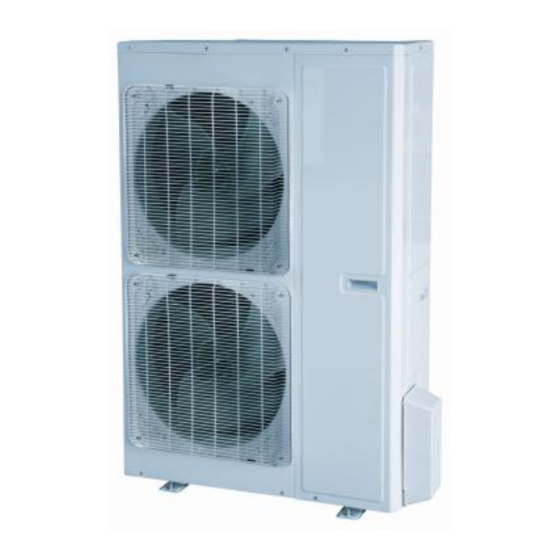
OUTDOOR UNITS
Type
INDOOR UNITS
DUCT
Type
INDOOR UNITS
CASSETTE
Type
INDOOR UNITS
CEILING
PLEASE READ AND
UNDERSTAND THIS MANUAL
BEFORE USING THIS
INVERTER-DRIVEN AIR
CONDITIONING UNIT. KEEP
THIS MANUAL FOR FUTURE
REFERENCE.
Model
DHR18CSB21S
DHR24CSB21S
DHR30CSB21S
DHR36CSB21S
DHR42CSB21S
DHR48CSB21S
Model
DHR18NDB21S
DHR24NDB21S
DHR30NDB21S
DHR36NDB21S
DHR42NDB21S
DHR48NDB21S
Model
DHR18NKB21S
DHR24NKB21S
DHR30NKB21S
DHR36NKB21S
DHR42NKB21S
DHR48NKB21S
Model
DHR18NCB21S
DHR24NCB21S
DHR30NCB21S
DHR36NCB21S
DHR42NCB21S
DHR48NCB21S
Advertisement
Table of Contents
Troubleshooting

Related Manuals for Johnson Controls R SERIES


Summary of Contents for Johnson Controls R SERIES
- Page 1 Installation Maintenance Manual "R" SERIES INVERTER-DRIVEN AIR CONDITIONING UNITS Type Model DHR18CSB21S DHR24CSB21S OUTDOOR UNITS DHR30CSB21S DHR36CSB21S DHR42CSB21S DHR48CSB21S Type Model DHR18NDB21S DHR24NDB21S INDOOR UNITS DHR30NDB21S DUCT DHR36NDB21S DHR42NDB21S DHR48NDB21S Model Type DHR18NKB21S DHR24NKB21S INDOOR UNITS DHR30NKB21S CASSETTE DHR36NKB21S DHR42NKB21S DHR48NKB21S Type Model...
-
Page 2: Important Notice
Important Notice ● Johnson Controls, Inc. pursues a policy of continuing improvement in design and performance in its products. As such, Johnson Controls, Inc. reserves the right to make changes at any time without prior notice. ● Johnson Controls, Inc. cannot anticipate every possible circumstance that might involve a potential hazard. -
Page 3: Table Of Contents
Table of Contents 1. INTRODUCTION AND SAFETY SUMMARY ..................i 2. INDOOR UNIT INSTALLATION ........................1 2.1 Installation of Duct Type ......................... 1 2.2 Installation of Floor Ceiling Type ....................10 2.3 Installation of Cassette Type ......................16 3. OUTDOOR UNIT INSTALLATION......................26 3.1 Before Installation .......................... 26 3.2 Installation Site ..........................26 3.3 Caution for Installation ......................... -
Page 4: Important Safety Instructions
Never bypass or jump-out any safety device or switch. ● Johnson Controls, Inc. will not assume any liability for injuries or damage caused by not following steps outlined or described in this manual. Unauthorized modifications to Johnson Controls products are prohibited as they…... - Page 5 Take the following precautions to reduce the risk of property damage. ● Be careful that moisture, dust, or variant refrigerant compounds not enter the refrigerant cycle during installation work. Foreign matter could damage internal components or cause blockages. ● If air filters are required on this unit, do not operate the unit without the air filter set in place. If the air filter is not installed, dust may accumulate and breakdown may result.
- Page 6 Controls uses only refrigerants that have been approved for use in the unit’s intended home country or market. Johnson Controls distributors similarly are only authorized to provide refrigerants that have been approved for use in the countries or markets they serve. The refrigerant used in this unit is identified on the unit’s faceplate and/or in the associated manuals.
- Page 7 under pressure and never open pressurized system parts. ● Before installation is complete, make sure that the refrigerant leak test has been performed. If refrigerant gases escape into the air, turn OFF the main switch, extinguish any open flames and contact your service contractor.
- Page 8 ● Communication cabling shall be a minimum of 18-Gauge, 2-Conductor, Stranded Copper. Shielded cable must be considered for applications and routing in areas of high EMI and other sources of potentially excessive electrical noise to reduce the potential for communication errors. When shielded cabling is applied, proper bonding and termination of the cable shield is required as per Johnson Controls guidelines.
-
Page 9: Indoor Unit Installation
2. INDOOR UNIT INSTALLATION 2.1 Installation of Duct Type 2.1.1 Before Installation After receiving the machine, please check for any transport damage. If finding any surface or internal damage, please immediately report to the transport company or equipment company in writing. After receiving the machine, please check the unit and accessories in reference to the packing list. - Page 10 drawing of the indoor unit for the distance between the holes. Refer to Figure 3-1-1 for the installation of the expansion bolt. Air-conditioning Unit Ceiling-mount Screw Hanger Figure 3-1-1 Figure 3-1-2 Screw Hook Figure 3-1-3 Install the hanger onto the indoor unit as Figure 3-1-2 and Figure 3-1-3 shows. Install the indoor unit at the ceiling as Figure 3-1-4 shows.
- Page 11 Level Instrument Condensate Air Intake Air Supply Pipes As the inside of the unit is in the negative Enlarged View pressure status, it is required to set up a Condensate Pipe backwater elbow. The requirement is: A=B≥(0.145P/10000+20)/25.4(inch) P is the absolute pressure inside the unit. The unit of the pressure is psig.
- Page 12 For the units: 48k Figure 3-1-6 Table 3-1-1 Unit: mm (inch) Item Model 1037 DHR18NDB21S (37-1/4) (24-3/8) (29) (35-1/8) (40-7/8) (28-3/8) (29) (4-7/8) (10-1/2) 1101 1159 1279 1002 DHR24NDB21S (43-3/8) (20-3/8) (32-1/4) (45-5/8) (50-3/8) (22) (39-1/2) (6-1/4) (9-1/4) (10-1/2) DHR30NDB21S 1011 1115 1226...
-
Page 13: Installation Clearance Data
2.1.5 Installation Clearance Data Nut with Nut Spring Washer Washer G 250mm G 250mm (9-7/8inch) (9-7/8inch) Figure 3-1-7 Warning! The height of installation for the indoor unit should be 2.5m (8-1/5ft) above. 2.1.6 Condensate Piping Work Installation of Condensate Pipeline: Install the condensate hose in accordance with the instructions in this installation manual and keep the a rea warm enough to prevent condensation. - Page 14 Supporter 1~1.5m(3-2/7~5feet) Condensate hose Figure 3-1-9 Figure 3-1-10 Condensate Pipe As the inside of the unit is in the negative pressure status, it is required to set up a backwater elbow. The requirement is: Enlarged View A=B≥(0.145P/10000+20)/25.4(inch) Condensate Pipe P is the absolute pressure inside the unit.
- Page 15 Condensate hose insulation Insulated condensate hose Condensate hose insulation Drain cap Unit Drain port Unit 0mm(0inch) Drain port 0mm(0inch) Drain cap Insulated Condensate hose Figure 3-1-13 Figure 3-1-14 (11) There is adhesive on one side of the insulation so that after removing the protective paper over it the insulation can be directly attached to the condensate hose.
- Page 16 T-joint converging condensate pipes T-joint converging condensate pipes Figure 3-1-17 2.1.7 Installation of air duct Dimensions of the Supply Air Outlet/Return Air Inlet 21mm(7/8inch) Figure 3-1-18 Supply Air Outlet Figure 3-1-19 Return Air Inlet Table 3-1-3 Unit: mm (inch) Supply Air Outlet Return Air Inlet Item Model...
- Page 17 2.1.8 Installation of the Supply Air Duct (1) Installation of the Rectangular Duct. Table 3-1-4 Installation of the rectangular duct Name Name Hanger Filter Main Air Air Intake Pipe Supply Pipe Air Supply Canvas Air Pipe Outlet Air Intake Figure 3-1-20 .
-
Page 18: Installation Of Floor Ceiling Type
maintenance etc., as shown in Figure 3-1-22. Supply air Supply air Return air Return air Install the return air duct(a) Install the return air duct(b) Figure 3-1-22 Table 3-1-5 Installation of the return air duct Name Name Return Air Inlet (with filter) Indoor unit Canvas Duct Supply Air Duct... - Page 19 Floor type Ceiling type Figure 3-1-23 (4) Install the unit where the condensate pipe can be easily installed. (5) The space from the unit to the ceiling should be kept as much as possible so as for more convenient service. 2.2.3 Indoor Unit Installation (1) Determine the location of the hanger through the paper template, and then remove the paper template.
- Page 20 (3) First, unfix two buckles on the grille as shown on the picture. Remove the screws under the buckles by a screwdriver and then open the inlet grille. Remove the screw Figure 3-1-25 (4) Remove the screws shown in the picture. Push the side plate as per the arrow direction and take it down.
- Page 21 Ceiling type Ceiling Suspension bolt Spring washer Left side panel Right side panel Hanger Figure 3-1-28 (7) Adjust the height of the unit to make the condensate pipe slant slightly downward so that the drainage will become much smoother. 2.2.4 Leveling The water level test must be done after installing the indoor unit to make sure the unit is horizontal, as shown below.
- Page 22 2.2.5 Dimension Data Figure 3-1-30 Table 3-1-6 Unit: mm (inch) Model DHR18NCB21S 1220(48) 225(8-7/8) 1158(45-5/8) 280(11) 700(27-1/2) DHR24NCB21S DHR30NCB21S DHR36NCB21S 1420(55-7/8) 245(9-5/8) 1354(53-1/4) 280(11) 700(27-1/2) DHR42NCB21S 1700(66-7/8) 245(9-5/8) 1634(64-3/8) 280(11) 700(27-1/2) DHR48NCB21S 2.2.6 Condensate Piping Work 2.2.6.1 Precautions When Doing the Piping Work (1) Keep piping as short as possible and slope it downwards at a gradient of at least 1/100 so that air may not remain trapped inside the pipe.
- Page 23 (4) Connect the condensate hose (Figure 3-1-32). Condensate hose must slope downward. Allow no trap to form in the piping Do not allow end of hose to touch water Figure 3-1-32 2.2.6.2 Installing the Condensate Pipes (1) For determining the position of the condensate hose, perform the following procedures. (2) Insert the condensate pipe to the drain outlet of the unit and then tighten the clamp securely with tape (Figure 3-1-33).
-
Page 24: Installation Of Cassette Type
Condensate pan Condensate hose Bottom-right piping Right side piping Figure 3-1-36 2.2.6.4 Testing of Condensate Piping (1) After piping work is finished, check if drainage flows freely. (2) As shown in the figure, pour water into the condensate pan from the right side to check that water flows freely from the condensate hose. - Page 25 2.3.2 Installation Site Select an installation site where the following conditions are fulfilled and that meets your customer's approval. (1) Obstructions should be moved away from the intake or outlet vent of the indoor unit so that the airflow can be blown throughout the room.
- Page 26 2.3.3 Installing the Main Body Unit Nut(field supplied) Gas(attachment) Insert Gasket anchor board(attachment) Hoisting stand Tighten(double nuts) [Fix the gasket firmly] [Fix the hoisting stand firmly] One bolt located at one corner of the outlet pipe Center of the ceiling should be fixed on one corner of the drainage slot.
-
Page 27: The Panel Installation
2.3.5 Leveling The water level test must be done after installing the indoor unit to make the unit is horizontal, as shown below. Horizontal tester Figure 3-1-43 2.3.6 The Panel Installation (1) See the figure below for the positions of the front panel and the connecting pipe. Figure 3-1-44 (2) Place the panel at the unit, and latch the hooks beside and opposite the swing flap motor. - Page 28 Hook Latch Piping position Swing flap motor Indoor unit Ceiling Indoor unit 5~8mm(1/4~3/8inch) Panel Air outlet Figure 3-1-45 (7) Improper screwing of the screws may cause the troubles shown in Figure 3-1-46. Air leak Condensate Figure 3-1-46 (8) If gap still exists between ceiling and decorative panel after tightening the screws, readjust the height of the indoor unit (Figure 3-1-47).
- Page 29 (9) Wire the swing flap motor as shown in Figure 3-1-48. Connect them to the main body according to the size of terminals Figure 3-1-48 2.3.7 Dimension Data For the units: 18k Table 3-1-8 Unit: mm (inch) Item Model DHR18NKB21S (26-3/8) (23-1/2) (23-1/4)
-
Page 30: Installation Of Condensate Piping
Unit: mm (inch) Item Model DHR24NKB21S (37-3/8) (33-1/8) (30-3/4) (26-3/4) (6-1/4) (9-1/2) (36-1/8) (8-1/2) (39-1/8) DHR30NKB21S (37-3/8) (33-1/8) (30-3/4) (26-3/4) (6-1/4) (12-5/8) (36-1/8) (8-1/2) (39-1/8) DHR36NKB21S (37-3/8) (33-1/8) (30-3/4) (26-3/4) (6-1/4) (12-5/8) (36-1/8) (8-1/2) (39-1/8) DHR42NKB21S (37-3/8) (33-1/8) (30-3/4) (26-3/4) (6-1/4) (12-5/8)) (36-1/8)) - Page 31 2.3.9 Installing the Condensate Pipes (1) Insert the condensate pipe to the drain outlet of the unit and then tighten the clamp securely with tape. (2) Connect the extension condensate pipe to the condensate pipe and then tighten the clamp with tape.
- Page 32 (8) Connection of drainage branch pipe to the standpipe or horizontal pipe of drainage main pipe. (9) The horizontal pipe cannot be connected to the vertical pipe at a same height. It can be connected in a manner as shown below: NO.1: Attach the 3-way connection of the condensate pipe joint as shown in Figure 3-1-55.
- Page 33 1~1.5m(3-2/7~5feet) × (wrong ) √ (Correct) 1/100 or more gradient Figure 3-1-59 (5) The incline of attached condensate hose should be 75mm (3inch) or less so that the drain outlet does not have to withstand additional force. Condensate hose(attachment) Figure 3-1-60 2.3.11 Testing of Condensate Piping After piping work is finished, check if drainage flows freely.
-
Page 34: Outdoor Unit Installation
3. OUTDOOR UNIT INSTALLATION 3.1 Before Installation After receiving the unit, please check for any transport damage. If finding any surface or internal damage, please immediately report to the transport company or equipment company in writing. After receiving the machine, please check the unit and accessories in reference to the packing list. Ensure that the model is correct and the unit is in good condition. -
Page 35: Caution For Installation
2000mm 500mm (6-5/9feet) (1-2/3feet) Figure 3-2-1 3.3 Caution for Installation The outdoor unit should be so installed that the air discharged out of the outdoor unit will not flow back and that enough space shall be maintained around the machine for repair. The installing position should allow good ventilation so that the machine can breathe and exhaust enough air. -
Page 36: Refrigeration Piping Work
Table 3-2-1 Unit: mm (inch) Item Model DHR18CSB21S (37-5/8) (15-5/8) (27-1/2) (22) (14-1/8) DHR24CSB21S (38-5/8) (16-3/4) (31-1/8) (24) (15-1/2) DHR30CSB21S 1107 1100 DHR36CSB21S (43-5/8) (17-3/8) (43-1/4) (24-7/8) (15-3/4) DHR42CSB21S 1349 (37-3/4) (16-1/4) (53-1/8) (22-1/2) (14-3/4) DHR48CSB21S 4. REFRIGERATION PIPING WORK 4.1 Refrigeration Piping Work Procedures and Caution in Connecting 4.1.1 Flare Processing (1) Cut the connection pipe with the pipe cutter and remove the burrs. - Page 37 stretch them any more. Do not bend or stretch the pipes more than three times. (4) When bending the pipe, do not bend it as is. The pipe will be collapsed. In this case, cut the heat insulating pipe with a sharp cutter as shown in Figure 3-3-3, and bend it after exposing the pipe. After bending the pipe as you want, be sure to put the heat insulating pipe back on the pipe, and secure it with tape.
- Page 38 Sponge Threaded fastener(×4) Heat insulation sheath (for the liquid tube) Heat insulation sheath (for the gas tube) Gas inlet pipe Liquid pipe Figure 3-3-4 Table 3-3-1 Flare nut tightening torque Pipe Diameter Tightening Torque 6mm (1/4inch) 15~30N·m (11~22ft.-1b.) 9.5mm (3/8inch) 35~40N·m (26~29ft.-1b.) 12.7mm (1/2inch) 45~50N·m (33~37ft.-1b.)
-
Page 39: Vacuum And Gas Leakage Inspection
4.1.5 Checking the Pipe Connections for Gas Leaking For both indoor and outdoor unit side, check the joints for gas leaking by the use of a gas leakage detector without fail when the pipes are connected. 4.1.6 Heat Insulation on the Pipe Joints (Indoor Side Only) Stick coupler heat insulation (large and small) to the place where connecting pipes. -
Page 40: Additional Charge
(7) Slightly open the liquid valve and let some refrigerant go to the connection pipe to balance the pressure inside and outside of the connection pipe, so that air will not come into the connection pipe when removing the hose. Note that the gas and liquid valve can be opened fully only after the manifold valve assembly is removed. -
Page 41: Specification Of Connection Pipe
an oil bend should be employed for every 6m (19-2/3 feet). Outdoor Oil bend Indoor Oil bend Figure 3-3-8 4.2 Specification of Connection Pipe Table 3-3-3 Size of Fitting Pipe Max. Height Difference Drainage pipe(Outer Item Max. Pipe mm (inch) between Indoor Unit and Diameter ×... -
Page 42: Electrical Wiring
. The power source capacity must be the sum of the air conditioner current and the current of other electrical appliances. When the current contracted capacity is insufficient, change the contracted capacity. 8. When the voltage is low and the air conditioner is difficult to start, contact the power company to raise the voltage. 5.2 Electrical Wiring (1) For solid core wiring (Figure 3-4-1) Cut the wire end with a wire cutter or wire-cutting pliers, then strip the insulation about 25mm (1... - Page 43 clamp (Figure 3-4-3). . Before starting work, check that power is not being supplied to the indoor unit and outdoor unit. . Match the terminal block numbers and connection cord colors with those of the indoor unit side. Erroneous wiring may cause burning of the electric parts.
- Page 44 Cassette Type Unit: Single-phase units: 18k Single-phase units: 24k~30k Single-phase units: 36k~42k...
- Page 45 Single-phase units: 48k Floor ceiling Type Unit: Single-phase units (18k~30k) Single-phase units (36k~48k) Figure 3-4-4...
- Page 46 (5) Electric wiring of indoor unit side Remove the electric box cover from the electric box sub-assy and then connect the wire. Duct Type Unit: L1 L2 H1 H2 Electric box sub-assy Figure 3-4-5 The F, C, O connect to the COMMOM, CLOSE and OPEN terminal of the fresh air valve respectively. Cassette Type Unit: For the units: 18k~42k...
- Page 47 For the units: 48k H1 H2 Figure 3-4-6 Floor Ceiling Type Unit: Electric box cover H1 H2 Figure 3-4-7 . The power cord and the wire of the fresh air valve are high-voltage, while the communication cord and connection wire of the wired zone controller are low-voltage. They should run separately against electromagnetic interference. 8.
- Page 48 . The high-voltage and low-voltage lines should be fixed separately and securely, with internal big clamps for the former and small clamps for the latter. . Tighten the indoor/outdoor connection cord and power cord respectively on the terminal boards with screws. Faul ty connection may cause a fire.
-
Page 49: Maintenance Troubleshooting
6. MAINTENANCE TROUBLESHOOTING ERROR CODES TABLE 6.1 Main Control Malfunction Table 4-1-1 Fault Display on Indoor Wired Zone Controller Malfunction Origin of Error code Control description name malfunction signal When outdoor unit detects the high pressure switch is cut off for 3s successively, high pressure protection will occur. - Page 50 Malfunction Origin of Error code Control description name malfunction signal If cut-off of water level switch is detected for 8s successively once Full water energized, the system will enter full water protection. In this case, Water level switch protection switch off the unit and then switch it on to eliminate this malfunction.
-
Page 51: Description Of Drive Malfunction
Malfunction Origin of Error code Control description name malfunction signal If outdoor unit detects that the tube temperature is higher than protective temp. value, the unit will report overload protection. Evaporator The unit will not restart operation until tube temperature is lower Overload temperature, than the protective temp. - Page 52 6.2 Description of Drive Malfunction Main board dual 8 numeral tube Display Codes for Outdoor Unit of 18k~48k Outdoor unit display of dual 8 numeral Malfunction Item Indoor Unit Display tube DC busbar over-voltage protection IPM or PFC over-temperature protection Current sense circuit error IPM or PFC temperature sensor error Compressor current protection...
-
Page 53: Flow Chart Of Troubleshooting
7. FLOW CHART OF TROUBLESHOOTING 7.1 Troubleshooting Flow Chart of Main Control Malfunction E1 High Pressure Protection... - Page 54 E2 Freeze Protection Freeze protection is normal protection but not abnormal malfunction. If freeze protection occurs frequently during operation, please check if the indoor filter is dirty or if the indoor air outlet is abnormal. The user is required to clean the filter, check the air outlet and air return pipe periodically to ensure smooth air return and air outlet.
- Page 55 E4 Discharge Protection E6 Communication Malfunction Communication malfunction Check if the Reconnect the communication wire between communication indoor unit and outdoor unit is wire connected well Check if there is Replace the open circuit in the communication communication wire between indoor unit and wire outdoor unit Check if the...
- Page 56 E9 Full Water Protection E9 protection Short circuit the full water If the unit is protection interface on indoor installed with mainboard according to the circuit water pump diagram Check if the water pump Replace the water pump works normally Replace the full water switch or make sure the float of full water switch works normally...
- Page 57 F1 Malfunction of Evaporator Temperature Sensor Malfunction of evaporator temperature sensor Check if the evaporator Correctly insert the temperature sensor on temperature mainboard is inserted on the sensor on the needle stand correctly needle stand Disconnect Replace the the temperature sensor and temperature measure if its resistance is sensor...
- Page 58 F3 Malfunction of Outdoor Ambient Temperature Sensor Malfunction of outdoor ambient temperature sensor Check Correctly insert the if the outdoor ambient temperature sensor on temperature sensor on mainboard the needle stand is inserted on the needle stand correctly Disconnect Replace the the temperature sensor and temperature sensor measure if its resistance is...
- Page 59 F5 Malfunction of Wired Controller Temperature Sensor Malfunction of wired controller temperature sensor Replace the wired controller H6 Malfunction of Outdoor Fan Motor...
-
Page 60: Troubleshooting Flow Chart Of Drive Malfunction
E8 Malfunction of Indoor Fan Motor Malfunction of indoor fan motor Check if the Correctly connect the control wire of indoor fan motor is control wire of fan motor connected on the outdoor on the mainboard mainboard correctly Replace the indoor fan motor and then Operate the unit with restart the unit to see if there still the new motor... - Page 61 P8 IPM or PFC over-temperature protection P8 is displayed on wired zone controller P8 is displayed in the mainboard 88 Indicating light Is the IPM or PFC module of mainboard tightened Replace the Tighten the IPM mainboard or PFC module Works normally PH DC busbar over-voltage protection PL DC busbar under-voltage protection...
- Page 62 P6 Drive-to-main-control communication error Lc Compressor Startup Failure Lc is displayed on the wired controller Lc is displayed in the mainboard 88 indicating light Replace the mainboard. Does it work normally? Replace the compressor Works normally P5 Compressor current protection H7 Compressor motor desynchronizing H5 IPM protection Ld Phase loss...
- Page 63 PU Charging circuit error PU is displayed on wired zone controller PU is displayed in the mainboard 88 indicating light Is the PFC wire tightened or is the sequence right? Tighten the PFC Replace the wire or adjust the mainboard sequence Works normally ee driving board chip error...
- Page 64 H6 DC fan error...
-
Page 65: Interface
7.3 Interface DHR18CSB21S / DHR24CSB21S / DHR30CSB21S / DHR36CSB21S / DHR42CSB21S / DHR48CSB21S Main Control Board NO. SILK-SCREEN INTERFACE INTERFACE INSTRUCTION AC-L Live wire input Live wire input AC-N Neutral wire input Neutral wire input Power supply interface to the drive Control power output[1- DC bus PWR 1 1-pin: DC bus voltage... - Page 66 Communication needle stand of main control drive Communication line [1-3.3V 2-TX 1-pin: +3.3V COMM1 3-RX 4-GND] 2-pin: TXD 3-pin: RXD 4-pin: GND Communication needle stand with indoor unit Communication line with1-pin 1-pin: GND GND, 2-pin B and 3-pinA 2-pin: B 3-pin: A Communication interface...
- Page 67 DHR18CSB21S / DHR24CSB21S / DHR30CSB21S / DHR36CSB21S / DHR42CSB21S (1) Driving Board Printing Interface Printing Interface L2_2 PFC induction wire (blue) L1_1 PFC induction wire (brown) Neutral wire input (white) AC-L Live wire input (red) COMM/COMM1 Communication interface JTAG1 (Reserved) Bus electric discharging interface (for Control power input DC-BUS1...
- Page 68 Filtering Board Printing Interface Printing Interface Neutral wire output 1 (white) (only for Neutral wire output N-OUT1 N-OUT 18k) (white) L-OUT Live wire output (red) Grounding wire (Reserved) AC-L Live wire input (red) AC-N Neutral wire input (white)
- Page 69 DHR48CSB21S (1) Drive Board: Printing Interface Printing Interface AC-L Live wire input (red) L1-1 PFC induction wire (brown) Neutral wire input (white) L2-2 PFC induction wire (blue) L2-1 PFC induction wire (yellow) L1-2 PFC induction wire (white) Control power input JTAG1 (Reserved) DC bus electric discharging needle...
- Page 70 (2) Filtering Board: Printing Interface Printing Interface N-OUT Neutral wire output (white) L-OUT Live wire output (red) DC-BUS DC bus interface (connect to drive board) AC-L Live wire input (red) Neutral wire input (white) (Reserved) Grounding wire (screw hole)
-
Page 71: Ipm, Pfc Testing Method
7.4 IPM, PFC Testing Method 7.4.1 Method of Testing IPM Module (1) Preparation before test: Prepare a universal meter and turn to its diode option, and then remove the wires U, V, W of the compressor after it is powered off for one minute. (2) Testing Steps Step 1: Put the black probe on the place of P and the red one on the wiring terminal U, V, W respectively as shown in the following figure to measure the voltage between UP, VP and WP. -
Page 72: Wiring Diagram
DHR48CSB21S 8. WIRING DIAGRAM 8.1 Outdoor unit The actual wiring should always refer to the wiring diagram of the unit. Model: DHR18CSB21S... - Page 73 Model: DHR24CSB21S Model: DHR30CSB21S...
- Page 74 Model: DHR36CSB21S Model: DHR42CSB21S...
-
Page 75: Indoor Unit
Model: DHR48CSB21S 8.2 Indoor unit The actual wiring should always refer to the wiring diagram of the unit. 8.2.1 Duct Type Model: DHR18NDB21S / DHR24NDB21S / DHR30NDB21S / DHR36NDB21S / DHR42NDB21S... -
Page 76: Floor Ceiling Type
Model: DHR48NDB21S 8.2.2 Floor Ceiling Type Model: DHR18NCB21S /DHR24NCB21S /DHR30NCB21S / DHR36NCB21S / DHR42NCB21S / DHR48NCB21S... -
Page 77: Cassette Type
8.2.3 Cassette Type Model: DHR18NKB21S Model: DHR24NKB21S / DHR30NKB21S / DHR36NKB21S / DHR42NKB21S... - Page 78 Model: DHR48NKB21S...
- Page 80 Product improvement, specifications and appearance in this manual are subject to change without prior notice. LIT - 12012157 © Johnson Controls, Inc. USA...
Need help?
Do you have a question about the R SERIES and is the answer not in the manual?
Questions and answers