Table of Contents
Advertisement
CLICK ANYWHERE on THIS PAGE to RETURN to COLEMAN HVAC
HISTORY & GUIDES at InspectApedia.com
carefully before installation and operation and retain it for
"M" and "W" Series
Multi Zone System
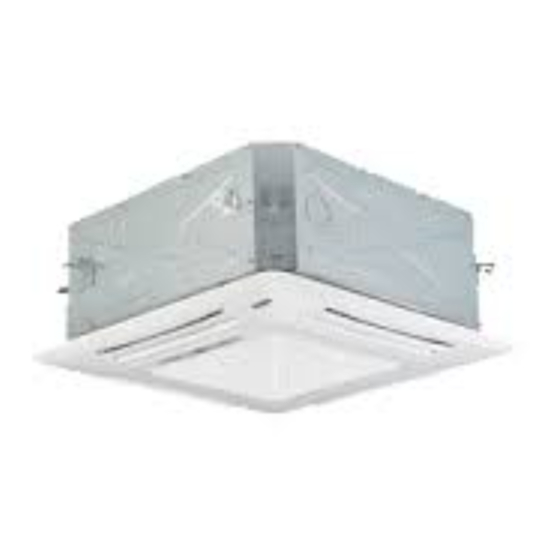
Compact Panel Cassette Type
Air Conditioning Units
Please read this Installation and Operation manual
12K - 18K
Indoor Units
Owner's Manual
Models:
DHMW12NKB21S
DHMW18NKB21S
future reference.
Advertisement
Table of Contents

Related Manuals for Johnson Controls DHMW12NKB21S


Summary of Contents for Johnson Controls DHMW12NKB21S
- Page 1 "M" and "W" Series 12K - 18K Multi Zone System Compact Panel Cassette Type Indoor Units Owner's Manual Air Conditioning Units Models: DHMW12NKB21S DHMW18NKB21S Please read this Installation and Operation manual carefully before installation and operation and retain it for future reference.
- Page 2 Important Notice ● Johnson Controls, Inc. pursues a policy of continuing improvement in design and performance in its products. As such, Johnson Controls, Inc. reserves the right to make changes at any time without prior notice. ● Johnson Controls, Inc. cannot anticipate every possible circumstance that might involve a potential hazard.
-
Page 3: Table Of Contents
Table of Contents Introduction and Safety Information...............i 1 Additional Usage Information ..............1 2 Installation of Compact Panel Cassette Indoor Unit ......... 2.1 Schematic diagram of installation spaces ............2 2.2 Select installation location of indoor unit ............. 2 2.3 Important notice ....................3 2.4 Dimensions of ceiling opening and location of threaded mounting rod ..... - Page 4 Never bypass or jump-out any safety device or switch. ● Johnson Controls, Inc. will not assume any liability for injuries or damage caused by not following steps outlined or described in this manual. Unauthorized modifications to Johnson Controls products are prohibited as they…...
- Page 5 Take the following precautions to reduce the risk of property damage. ● Be careful that moisture, dust, or variant refrigerant compounds not enter the refrigerant cycle during installation work. Foreign matter could damage internal components or cause blockages. ● If air filters are required on this unit, do not operate the unit without the air filter set in place. If the air filter is not installed, dust may accumulate and breakdown may result.
- Page 6 Controls uses only refrigerants that have been approved for use in the unit’s intended home country or market. Johnson Controls distributors similarly are only authorized to provide refrigerants that have been approved for use in the countries or markets they serve. The refrigerant used in this unit is identified on the unit’s faceplate and/or in the associated manuals.
- Page 7 under pressure and never open pressurized system parts. ● Before installation is complete, make sure that the refrigerant leak test has been performed. If refrigerant gases escape into the air, turn OFF the main switch, extinguish any open flames and contact your service contractor.
- Page 8 ● Communication cabling shall be a minimum of 18-Gauge, 2-Conductor, Stranded Copper. Shielded cable must be considered for applications and routing in areas of high EMI and other sources of potentially excessive electrical noise to reduce the potential for communication errors. When shielded cabling is applied, proper bonding and termination of the cable shield is required as per Johnson Controls guidelines.
-
Page 9: Additional Usage Information
Additional Usage Information ◆ When purchasing or installing multi-zone DFS systems the combination ratio must not exceed 150% of outdoor unit capacity. If the connecting indoor units exceed the recommended combination ratio then capacity will be greatly reduced and may damage the system. than 150% of the outdoor unit. -
Page 10: Installation Of Compact Panel Cassette Indoor Unit
Wall Wall surface surface ≥1500 ≥1500 Model DHMW12NKB21S unit:mm DHMW18NKB21S Ground surface Fig. 1 2.2 Select installation location of the indoor unit (1). There should be no obstructions near the intake or outlet vent of the indoor unit as this may restrict airflow. -
Page 11: Important Notice
22-1/2" 15-3/4" 22-1/2" 23-3/4" 25-1/2" Fig. 2 Installation Dimension of Models DHMW12NKB21S DHMW18NKB21S ◆ The drilling of holes in the ceiling must be done by a certified Installation stands for main body of the unit technician. Ceiling At least 13/16"... -
Page 12: Connection Of Refrigerant Piping
Installation of Compact Panel Cassette Indoor Unit ◆ Install the cardboard template on the unit with bolts (three) and check the angle of the condensate outlet. (3). Mount the unit to the previously installed threaded mounting rod. (Refer to Fig.3 above) (4). -
Page 13: Condensate Hose
Installation of Compact Panel Cassette Indoor Unit Ensure that the insulating material is securely fastened to the piping connections Torque wrench Insulating material must cover the piping completely Wrench Insulating material must cover the piping completely Suction line tubing Liquid line tubing Flare nut Fig. - Page 14 Installation of Compact Panel Cassette Indoor Unit hose Fig. 7 Drain step-up pipe note: ◆ The installation height of the condensate pipe riser should be less than 11 in. (280mm). ◆ The condensate pipe riser should form a right angle with the unit, and distance to unit should not be beyond 11.8 in.
-
Page 15: Electrical Wiring
Fig.12 Outdoor to indoor recommended cabling Power Supply Min. Size for Ground Min. Size for High Volt. Model (V, Ph, Hz) Wire(AWG) Comm Wiring (AWG) DHMW12NKB21S 208~203V-1Ph-60Hz UL1015 AWG 14*1 UL1015 AWG 18*3 DHMW18NKB21S 208~203V-1Ph-60Hz UL1015 AWG 14*1 UL1015 AWG 18*3... -
Page 16: Grille Installation
Installation of Cassette Grille Panel 2.9 Grille Installation (1). Install the grille onto the indoor unit body by matching the position of the swing flap motor of the panel to the piping position of the grille as shown in Fig. 13. ①... - Page 17 Installion of Indoor Unit Cassette Grille Air leak Air leak from ceiling Water condensatation, water drop Fig.14 ② . I f gaps exist between the ceiling and the cassette grille, and these cannot be eliminated with the corner screw adjustments, , then the cassette chassis needs to be adjusted lower for proper sealing of grille to chassis.
-
Page 18: Nomenclature Of Compact Panel Cassette Indoor Unit
Nomenclature of Compact Panel Cassette Indoor Unit 3 Nomenclature of Compact Panel Cassette Indoor Unit Condensate hose DHMW12NKB21S DHMW18NKB21S... -
Page 19: Working Temperature Range
Working Temperature Range 4 Working Temperature Range Working Temperature Range Indoor side state Outdoor side stae Dry bulb Wet bulb Dry bulb Wet bulb temp. ℃ temp. ℃ temp. ℃ temp. ℃ Rated Cooling Max. cooling Min. cooling — Rated Heating Max. -
Page 20: Troubleshooting Malfunctions
Troubleshooting Malfunctions 5 Troubleshooting Malfunctions Warning! ◆ Disconnect power immediately if there is a strong burning smell or if abnormal noises are coming from the indoor or outdoor units. Contact the installing contractor or service provider to have the system evaluated. 5.1 Items to Check before Calling Service Provider Event Possible Causes... -
Page 21: Instructions
Checking Malfunctions 5.2 Instructions If all possible solutions have been explored and system is still not operating correctly, then the installing contractor or a local service provider will need to evaluate the system. 5.3 Operation Issues Considered Normal (based on mechanical and environmental factors) “Operation”... -
Page 22: System Maintenance
Maintenance Methods 6 System Maintenance When the air conditioning unit won’t be used for a long time, please turn off the main power supply of the air conditioning unit. Warning! ◆ Turn off the unit and turn off the main power supply when cleaning the air conditioning unit, otherwise electric shock or injury may happen. -
Page 23: Cleaning Air Inlet Grille
System Maintenance (5). Close the air inlet grille (Use reverse procedures from step 1 above.) Fig.20 Fig.19 6.2 Cleaning Air Inlet Grille (1). Open the air inlet grille. (Refer to the first step of "Clean Air Filter" above.) (2). Take out the air filter. (Refer to the second step of "Clean Air Filter" above.) (3). -
Page 24: Cleaning Of Surfaces And Louvers
Maintenance Methods Function and usage period for air purifying ◆ Could absorb CO, CO , benzene, aldehydes or odor of gasoline, etc. ◆ Could absorb unhealthy material such as dust, pollen, bacteria, or virus. ◆ Usage period is six months to one year. Replacement purifier should be ordered through your installer or service provider. -
Page 25: Support Contact Information
Support Contact Information Email Technical Support BE-VRFTechSupport@jci.com Support during installation, commissioning, service, and troubleshooting Customer BE-VRFCustomerService@jci.com Service Assistance ordering equipment, parts, and accessories Warranty BE-VRFWarranty@jci.com Assistance with warranty registration, claims, etc. warranty Application and Design BE-VRFApplicationDesign@jci.com Pre-sale assistance with equipment applications and design support, as well as use of Selection Tool For all functions mentioned above, please call: 1(844) 873-4445... - Page 26 Product improvement, specifications and appearance in this manual are subject to change without prior notice. LIT-12012200 © Johnson Controls, Inc. USA...
Need help?
Do you have a question about the DHMW12NKB21S and is the answer not in the manual?
Questions and answers