Table of Contents
Advertisement
Quick Links
Service
Manual
"R" SERIES
INVERTER-DRIVEN
AIR CONDITIONING UNITS
Type
OUTDOOR UNITS
Type
INDOOR UNITS
DUCT
Type
INDOOR UNITS
CASSETTE
Type
INDOOR UNITS
CEILING
PLEASE READ AND
UNDERSTAND THIS MANUAL
BEFORE USING THIS
INVERTER-DRIVEN AIR
CONDITIONING UNIT. KEEP
THIS MANUAL FOR FUTURE
REFERENCE.
Model
DHR18CSB21S
DHR24CSB21S
DHR30CSB21S
DHR36CSB21S
DHR42CSB21S
DHR48CSB21S
Model
DHR18NDB21S
DHR24NDB21S
DHR30NDB21S
DHR36NDB21S
DHR42NDB21S
DHR48NDB21S
Model
DHR18NKB21S
DHR24NKB21S
DHR30NKB21S
DHR36NKB21S
DHR42NKB21S
DHR48NKB21S
Model
DHR18NCB21S
DHR24NCB21S
DHR30NCB21S
DHR36NCB21S
DHR42NCB21S
DHR48NCB21S
Advertisement
Table of Contents
Troubleshooting

Related Manuals for Johnson Controls R Series


Summary of Contents for Johnson Controls R Series
- Page 1 Service Manual "R" SERIES INVERTER-DRIVEN AIR CONDITIONING UNITS Type Model DHR18CSB21S DHR24CSB21S OUTDOOR UNITS DHR30CSB21S DHR36CSB21S DHR42CSB21S DHR48CSB21S Type Model DHR18NDB21S DHR24NDB21S INDOOR UNITS DHR30NDB21S DUCT DHR36NDB21S DHR42NDB21S DHR48NDB21S Model Type DHR18NKB21S DHR24NKB21S INDOOR UNITS DHR30NKB21S CASSETTE DHR36NKB21S DHR42NKB21S DHR48NKB21S Type Model DHR18NCB21S...
- Page 2 Important Notice ● Johnson Controls, Inc. pursues a policy of continuing improvement in design and performance in its products. As such, Johnson Controls, Inc. reserves the right to make changes at any time without prior notice. ● Johnson Controls, Inc. cannot anticipate every possible circumstance that might involve a potential hazard.
-
Page 3: Table Of Contents
TABLE OF CONTENTS SAFETY SUMMARY..............................i 1 MODELS LIST ..............................1 1.1 Outdoor Unit ............................1 1.2 Indoor Unit ............................2 2 NOMENCLATURE ............................3 3 PRODUCT DATA ............................. 4 3.1 Product Data of Indoor Unit ......................4 3.2 Operation Range ..........................10 3.3 Electrical Data ........................... - Page 4 TABLE OF CONTENTS (cont'd) 11 FLOW CHART FOR TROUBLESHOOTING ................... 45 11.1 Troubleshooting Flow Chart of Main Control Malfunction ..........45 11.2 Troubleshooting Flow Chart of Drive Malfunction..............52 11.3 Interface ............................57 11.4 IPM, PFC Testing Method ......................63 12 DISASSEMBLY AND ASSEMBLY PROCEDURES FOR MAIN PARTS...........65 12.1 Outdoor Unit ............................
- Page 5 Never bypass or jump-out any safety device or switch. ● Johnson Controls, Inc. will not assume any liability for injuries or damage caused by not following steps outlined or described in this manual. Unauthorized modifications to Johnson Controls products are prohibited as they…...
- Page 6 Take the following precautions to reduce the risk of property damage. ● Be careful that moisture, dust, or variant refrigerant compounds not enter the refrigerant cycle during installation work. Foreign matter could damage internal components or cause blockages. ● If air filters are required on this unit, do not operate the unit without the air filter set in place. If the air filter is not installed, dust may accumulate and breakdown may result.
- Page 7 Controls uses only refrigerants that have been approved for use in the unit’s intended home country or market. Johnson Controls distributors similarly are only authorized to provide refrigerants that have been approved for use in the countries or markets they serve. The refrigerant used in this unit is identified on the unit’s faceplate and/or in the associated manuals.
- Page 8 under pressure and never open pressurized system parts. ● Before installation is complete, make sure that the refrigerant leak test has been performed. If refrigerant gases escape into the air, turn OFF the main switch, extinguish any open flames and contact your service contractor.
- Page 9 ● Communication cabling shall be a minimum of 18-Gauge, 2-Conductor, Stranded Copper. Shielded cable must be considered for applications and routing in areas of high EMI and other sources of potentially excessive electrical noise to reduce the potential for communication errors. When shielded cabling is applied, proper bonding and termination of the cable shield is required as per Johnson Controls guidelines.
-
Page 10: Models List
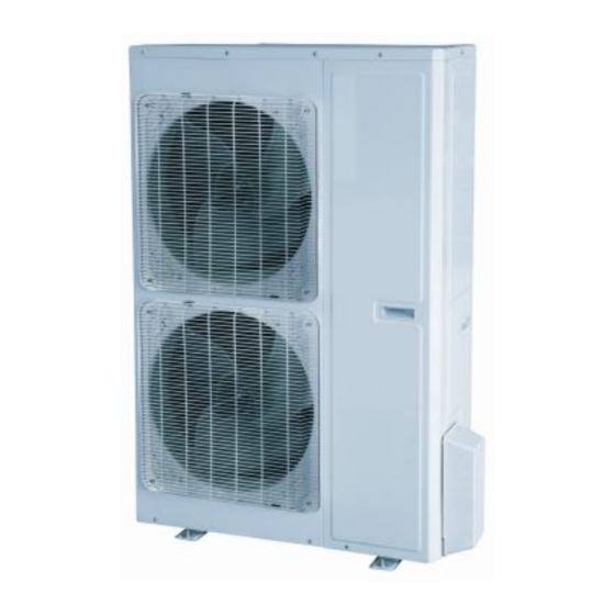
Service Manual PRODUCT 1 MODELS LIST 1.1 Outdoor Unit Power Supply Model Name Appearance (V, Ph, Hz) DHR18CSB21S 208/230V~60Hz DHR24CSB21S 208/230V~60Hz DHR30CSB21S 208/230V~60Hz DHR36CSB21S 208/230V~60Hz DHR42CSB21S 208/230V~60Hz DHR48CSB21S 208/230V~60Hz... -
Page 11: Indoor Unit
Service Manual 1.2 Indoor Unit Nominal Capacity Power Supply Type Model Name Cooling/Heating Appearance (V, Ph, Hz) (Btu/h) DHR18NDB21S 17100/18800 208/230V~60Hz DHR24NDB21S 23800/27200 208/230V~60Hz DHR30NDB21S 28200/31200 208/230V~60Hz Duct Type DHR36NDB21S 34000/41000 208/230V~60Hz DHR42NDB21S 39500/44000 208/230V~60Hz DHR48NDB21S 48000/54500 208/230V~60Hz DHR18NKB21S 17100/18400 208/230V~60Hz DHR24NKB21S 23800/27200... -
Page 12: Nomenclature
Service Manual 2 Nomenclature... -
Page 13: Product Data
Service Manual 3 PRODUCT DATA 3.1 Product Data of Indoor Unit 3.1.1 Duct Type DHR18NDB21S DHR24NDB21S DHR30NDB21S Indoor unit Model DHR18CSB21S DHR24CSB21S DHR30CSB21S Outdoor unit Cooling Capacity Btu/h 17100(5400~19800) 23800(7400~29000) 28200(8200~29600) Capacity Heating Capacity Btu/h 18800(4700~23200) 27200(8200~32400) 31200(8200~33600) Cooling 1.55(0.55~1.75) 2.23(0.85~2.50) 3.30(0.85~3.70) Power Input... - Page 14 Service Manual DHR36NDB21S DHR42NDB21S DHR48NDB21SI Indoor unit Model DHR36CSB21S DHR42CSB21S DHR48CSB21S Outdoor unit Cooling Capacity Btu/h 34000(10800~39000) 39500(12000~42500) 48000(20400~49500) Capacity Heating Capacity Btu/h 41000(9800~49500) 44000(13000~52500) 54500(17500~58000) Cooling 3.28(0.70~4.50) 4.15(0.65~4.70) 5.15(1.40~5.60) Power Input Heating 3.75(0.70~4.60) 3.90(0.76~4.75) 5.15(1.30~5.50) SEER / HSPF (Btu/h)/W 16.00/9.00 16.00/9.00 16.00/9.00...
- Page 15 Service Manual 3.1.2 Cassette Type DHR30NKB21S DHR18NKB21S DHR24NKB21S Indoor unit Model DHR18CSB21S DHR24CSB21S DHR30CSB21S Outdoor unit Cooling Capacity Btu/h 17100(5400~18700) 23800(8200~29000) 28200(8800~31400) Capacity Heating Capacity Btu/h 18400(4700~22200) 27200(8200~32400) 31200(8200~33600) Cooling 1.70(0.55~1.75) 2.23(0.85~2.50) 2.70(0.85~3.70) Power Input Heating 1.80(0.50~1.90) 2.36(0.80~2.75) 2.50(0.80~3.50) SEER / HSPF (Btu/h)/W 16.00/9.50 16.00/9.00...
- Page 16 Service Manual DHR48NKB21S DHR36NKB21S DHR42NKB21S Indoor unit Model DHR36CSB21S DHR42CSB21S DHR48CSB21S Outdoor unit Cooling Capacity Btu/h 34000(10800~39000) 39500(11000~41000) 48000(20400~50500) Capacity Heating Capacity Btu/h 41000(9800~49500) 44000(12000~51000) 54500(17500~61500) Cooling 3.28(0.75~4.50) 4.40(0.53~4.65) 5.50(1.30~5.70) Power Input Heating 3.75(0.60~4.80) 4.45(0.64~4.80) 4.80(1.20~5.40) SEER / HSPF (Btu/h)/W 16.00/9.00 16.00/9.00 16.00/9.00...
- Page 17 Service Manual 3.1.3 Floor-ceiling Type DHR18NCB21S DHR24NCB21S DHR30NCB21S Indoor unit Model DHR18CSB21S DHR24CSB21S DHR30CSB21S Outdoor unit Cooling Capacity Btu/h 17100(5400~19800) 23800(8200~27800) 28200(8800~31400) Capacity Heating Capacity Btu/h 19100(4700~23200) 27200(8200~30600) 31200(8200~33600) Cooling 1.55(0.55~1.75) 2.23(0.85~2.50) 2.40(0.85~3.70) Power Input Heating 1.55(0.50~1.90) 2.36(0.80~2.75) 2.60(0.80~3.50) SEER / HSPF (Btu/h)/W 17.00/9.50 16.00/9.00...
- Page 18 Service Manual DHR36NCB21S DHR42NCB21S DHR48NCB21S Indoor unit Model DHR36CSB21S DHR42CSB21S DHR48CSB21S Outdoor unit Cooling Capacity Btu/h 34000(10800~39000) 39500(12000~42500) 48000(20400~50500) Capacity Heating Capacity Btu/h 41000(9800~49500) 44000(13000~52500) 54500(17500~61500) Cooling 3.28(0.80~4.60) 4.05(0.60~4.70) 4.95(1.30~5.50) Power Input Heating 3.75(0.65~4.80) 4.05(0.69~4.80) 4.60(1.20~5.40) SEER / HSPF (Btu/h)/W 16.00/9.00 16.00/9.00 16.00/9.00...
-
Page 19: Operation Range
Service Manual 3.2 Operation Range Mode Range of Outdoor Temperature 0℉ (-18.0℃)~118.4℉ (48.0℃) Cooling 0℉ (-18.0℃)~75.2℉ (24.0℃) Heating 3.3 Electrical Data 3.3.1 Outdoor unit Table 1-3-1 Electrical Data of Outdoor Unit Minimum Maximum Compressor Fan Motor Fuse/Breaker Circuit Overcurrent Capacity Model Power Supply Qty. -
Page 20: Piping Diagram
Service Manual Note: RLA: Rated load amperes (marked in the nameplate of the outdoor unit) FLA: Full load amperes ① The fuse is located on the main board. ② Install the disconnect device with a contact gap of at least 3mm (1/8inch) in all poles near the outdoor unit.The outdoor unit must be positioned so that the disconnect is reachable from the unit.. -
Page 21: Control
Service Manual 5 CONTROLLERS OPERATION FLOWCHART 5.1 Cooling/Dry Operation Power Set controller to cool or dry mode Indoor fan run Comp. starts after 3min delay Comp. and outdoor fan run Temp of indoor ≤Set temp Comp. and outdoor fan stop Comp. -
Page 22: Heating Operation
Service Manual 5.2 Heating Operation Power Indoor unit running in heat mode Comp. starts after 3min delay Comp. and outdoor fan run Indoor fan starts only with hot coil Temp of indoor ≥Set temp Comp. and outdoor fan stop Comp. stop for 3 min... -
Page 23: Wireless Remote Controller
Service Manual 6 WIRELESS REMOTE CONTROLLER 6.1 Operation and Display View Table 2-2-1 Instructions for wireless remote controller Name Function Description Signal Signal transmitter transmitter Press this button and the unit will be turned on; press it once more and the unit will be ON/OFF turned off. - Page 24 Service Manual Preset temperature can be decreased by pressing this button. Pressing and holding this button for more than 2 seconds will quickly adjust the temperature until released. The temperature adjustment is unavailable under the Auto mode. Celsius setting range: 16° - button C~30°C;...
-
Page 25: Wired Controller
Service Manual Pressing this button can activate or deactivate the X-FAN function. In Cool or Dry mode, by pressing this button, if " " is displayed, it indicates the X-FAN function is activated. X-FAN By repressing this button, if " "... - Page 26 Service Manual Figure 2-3-2 LCD display of wired controller Table 2-3-1 Instruction to LCD Display Icons Introduction Left and right swing function Up and down swing function Air exchange function Sleep function Auto mode COOL mode DRY mode FAN mode HEAT mode Health function I-Demand function...
-
Page 27: Operation View
Service Manual Fan speed Memory function The unit will resume the original setting state after power is restored Turbo function Energy-saving function Ambient/setting temperature Electric heater Blow function (Coil drying function) Defrosting function (Heat Pump only) Filter cleaning reminder Timer Setting Keycard control / Motion Sensor Activation Quiet function Lock function... - Page 28 Service Manual 7.3.2 Button Functions Table 2-3-2 Wired Zone Controller Button Functions Description Functions ①. Function selection and canceling; ②. Press it for 5s to view the ambient temperature; press Mode button Enter/Cancel to select viewing outdoor ambient temperature or indoor ambient temperature.
- Page 29 Service Manual Note: The following functions can be set through Function and Timer buttons: setting of ambient temperature sensor, selecting three speeds in high speed and three speeds in low speed of indoor fan motor, display setting of freeze protection error code, setting of cold air prevention and hot air hot prevention function, setting of refrigerant-lacking protection function, selecting of blowing residual heat of indoor unit, selecting of compressor electric heater mode, selecting of low-power consumption mode, selecting door control function, selecting human sensitive function, long-...
-
Page 30: Special Functions Settings
Service Manual 7.2.3.2 Setting of Main/Secondary for Wired Zone Controllers With the indoor unit turned off, press Enter/Cancel and Mode buttons at the same time for 5s to go to the programming of main/secondary wired zone controller. Once in the program area, the LCD displays the wired zone controller‟s address (01 for main wired zone controller and 02 for secondary wired zone controller). - Page 31 Service Manual Setting of filter clean reminder function is shown as Figure 2-4-1 below: Figure 2-4-1 Setting of filter clean reminder function When setting the filter clean reminder function, timer zone will display 2 digits, of which the former indicates the pollution degree of operating place and the latter indicates the accumulated operating time of indoor unit.
-
Page 32: Low Temperature Drying Function
Service Manual accumulated operating time increases 400hr. When it reaches 9, it means the accumulated operating time is 5000hr; (4) High particulate: the former digit in timer zone shows 3 while the latter one shows 0, which indicates the accumulated operating time is 100hr. Each time the latter digit increases 1, the accumulated operating time increases 100hr. -
Page 33: Memory Function
Service Manual 8.4 Memory Function Press Mode and ▲ buttons at the same time for 5s under off state of the unit to turn on or cancel memory function. If memory function is set, is displayed. If not, indoor unit is defaulted to be off after power recovery. -
Page 34: Error Code Recall
Service Manual Note: ① If the unit is not connected to outdoor ambient temperature sensor, display of outdoor ambient temperature will be shielding after energizing for 12hr. ② If there is malfunction of outdoor ambient temperature sensor, display of outdoor ambient temperature will be shielding after energizing for 12hr. - Page 35 Service Manual 8.9.2 Freeze protection error code In the programming area, press Mode button until “02” is displayed on the controller. Press ▲ or ▼ button to adjust. There are two selections: (1) When activated controller displays "01" (2) When deactivated controller displays "02" This function may not apply to all models.
- Page 36 Service Manual operation state. 8.9.6 Selecting low-power consumption mode In the programming area, press Mode button until "07" is displayed at the controller. Press ▲ or ▼ button to scroll through selections: (1) With low-power consumption mode (LCD displays 00) (2) Without low-power consumption mode (LCD displays 01) 8.9.7 Selecting door control function In the programming area, press Mode button until "08"...
- Page 37 Service Manual Table 2-4-2 Combination relationship of P03, P04, P05, P06, P07 Static Super Quiet Quiet Quiet High Medium Medium Medium pressure high speed high speed low speed speed speed selection speed speed speed speed 8.9.11 Selecting compensation of temperature sensor at air return In the programming area, press Mode button until "12"...
-
Page 38: Central Controller
Service Manual Temperature excursion protection Low voltage protection of bus bar High voltage protection of bus bar Charging circuit malfunction Abnormity of input voltage Malfunction of outdoor drive memory chip When there is a malfunction during operation, error will be displayed at the controller. When several malfunctions occur at the same time, these error codes will be displayed as a sequence that can be scrolled through. - Page 39 Service Manual 9.1.2 Buttons and Display of Central Controller Figure 2-7-1 9.1.3 Function Buttons Table 2-7-1 Functions of Buttons Name Function Description Mode It is used for the switchover among different modes. It is used to set the fan speed, high, medium, low or auto. On/Off It is used to set the on/off status of the indoor unit.
- Page 40 Service Manual It is used for the switchover between unit 4and unit 12; 4/12 Under the timer or clock setting status, it indicates Thursday. It is used for the switchover between unit 5and unit 13; 5/13 Under the timer or clock setting status, it indicates Friday. It is used for the switchover between unit 6 and unit 14;...
- Page 41 Service Manual Table 2-7-2 Introduction to the Symbols on the LCD Name Description It displays the fan speed of the indoor unit, high, medium, low and Fan speed auto. It displays the running mode of the indoor unit, auto, cool, dry, fan and Running mode heat.
-
Page 42: Additional Special Functions
Service Manual 9.1.4.4 Dimensions Figure 2-7-5 9.2 Additional Special Functions 9.2.1 Door control function Door control function is available for this series. In order to carry out this function, please consult the Call Center for information on door control accessories. (Call Center Support information is on last page of this manual.) (1) Interface instructions The interface printing is DOOR-C and the type is B2B-XH-B. - Page 43 Service Manual Table 2-7-3 Door control wiring port Terminal name Terminal instruction CN1 wiring terminal and door control interface of indoor main board X1(AC-L, AC-N) wiring terminal, connected to door control input X1(AC-L, AC-N) signal, rated voltage 220V. X2 wiring terminal, connected to door control input signal (low voltage) (2) Function instructions: In order to achieve this function, set it through wired controller and refer to the following operation method.
- Page 44 Service Manual 9.2.2 Occupancy function You must purchase the occupancy module for this function to be activated. An interface for this module is reserved on the mainboard of indoor unit. (1) Interface instruction: The printing is CN23 and the interface type is JST B3B-PH-K-S; Electrical characteristic: 1-pin: +12V;...
- Page 45 Service Manual Figure 2-7-8 ("human sensitive" = "occupancy" Note: When the door control function and occupancy function have been set at the same time, it is defaulted that door control function is valid and occupancy function is invalid. The user can purchase the occupancy module as an accessory. Please pay attention to the following notes: ①...
- Page 46 Service Manual (3) Setting method: First, set the address mode of the wired zone controller into central controller address mode. The setting method is: 1) Under off state of the unit, press Function and Timer buttons at the same time for 5s to go to the programming menu.
- Page 47 Service Manual Figure 2-7-13...
- Page 48 Service Manual (2) Function instructions: In order to achieve this function, set the address mode and address through wired zone controller. Please refer to Point 3 below for the setting method. The address mode is defaulted to be connecting to central controller mode and the defaulted address is 1;...
- Page 49 Service Manual Under off state of the unit, press Function and Mode buttons simultaneously for 5s to enter setting interface of wired zone controller address. LCD displays address sequence. Press ▲ or ▼ button to adjust the address sequence and then press Enter/Cancel button to confirm. The setting value will be maintained after a power failure.
-
Page 50: Maintenance
Service Manual 10 MAINTENANCE AND TROUBLESHOOTING ERROR CODES TABLE 10.1 Main Control Malfunction Table 4-1-1 Fault Display on Indoor Wired Zone Controller Malfunction Origin of Error code Control description name malfunction signal When outdoor unit detects the high pressure switch is cut off for 3s successively, high pressure protection will occur. - Page 51 Service Manual Malfunction Origin of Error code Control description name malfunction signal If cut-off of water level switch is detected for 8s successively once Full water energized, the system will enter full water protection. In this case, Water level switch protection switch off the unit and then switch it on to eliminate this malfunction.
- Page 52 Service Manual Malfunction Origin of Error code Control description name malfunction signal If outdoor unit detects that the tube temperature is higher than protective temp. value, the unit will report overload protection. Evaporator The unit will not restart operation until tube temperature is lower Overload temperature, than the protective temp.
-
Page 53: Description Of Drive Malfunction
Service Manual 10.2 Description of Drive Malfunction Main board dual 8 numeral tube Display Codes for Outdoor Unit of 18k~48k Outdoor unit display of dual 8 numeral Malfunction Item Indoor Unit Display tube DC busbar over-voltage protection IPM or PFC over-temperature protection Current sense circuit error IPM or PFC temperature sensor error Compressor current protection... -
Page 54: Flow Chart For Troubleshooting
Service Manual 11 FLOW CHART FOR TROUBLESHOOTING 11.1 Troubleshooting Flow Chart of Main Control Malfunction E1 High Pressure Protection... - Page 55 Service Manual E2 Freeze Protection Freeze protection is normal protection but not abnormal malfunction. If freeze protection occurs frequently during operation, please check if the indoor filter is dirty or if the indoor air outlet is abnormal. The user is required to clean the filter, check the air outlet and air return pipe periodically to ensure smooth air return and air outlet.
- Page 56 Service Manual E4 Discharge Protection E6 Communication Malfunction Communication malfunction Check if the Reconnect the communication wire between communication indoor unit and outdoor unit is wire connected well Check if there is Replace the open circuit in the communication communication wire between indoor unit and wire outdoor unit...
- Page 57 Service Manual E9 Full Water Protection E9 protection Short circuit the full water If the unit is protection interface on indoor installed with mainboard according to the circuit water pump diagram Check if the water pump Replace the water pump works normally Replace the full water switch or make sure the float of full...
- Page 58 Service Manual F1 Malfunction of Evaporator Temperature Sensor Malfunction of evaporator temperature sensor Check if the evaporator Correctly insert the temperature sensor on temperature mainboard is inserted on the sensor on the needle stand correctly needle stand Disconnect Replace the the temperature sensor and temperature measure if its resistance is...
- Page 59 Service Manual F3 Malfunction of Outdoor Ambient Temperature Sensor Malfunction of outdoor ambient temperature sensor Check Correctly insert the if the outdoor ambient temperature sensor on temperature sensor on mainboard the needle stand is inserted on the needle stand correctly Disconnect Replace the the temperature sensor and...
- Page 60 Service Manual F5 Malfunction of Wired Controller Temperature Sensor Malfunction of wired controller temperature sensor Replace the wired controller H6 Malfunction of Outdoor Fan Motor...
-
Page 61: Troubleshooting Flow Chart Of Drive Malfunction
Service Manual E8 Malfunction of Indoor Fan Motor Malfunction of indoor fan motor Check if the Correctly connect the control wire of indoor fan motor is control wire of fan motor connected on the outdoor on the mainboard mainboard correctly Replace the indoor fan motor and then Operate the unit with... - Page 62 Service Manual P8 IPM or PFC over-temperature protection P8 is displayed on wired zone controller P8 is displayed in the mainboard 88 Indicating light Is the IPM or PFC module of mainboard tightened Replace the Tighten the IPM mainboard or PFC module Works normally PH DC busbar over-voltage protection PL DC busbar under-voltage protection...
- Page 63 Service Manual P6 Drive-to-main-control communication error Lc Compressor Startup Failure Lc is displayed on the wired controller Lc is displayed in the mainboard 88 indicating light Replace the mainboard. Does it work normally? Replace the compressor Works normally P5 Compressor current protection H7 Compressor motor desynchronizing H5 IPM protection Ld Phase loss...
- Page 64 Service Manual PU Charging circuit error PU is displayed on wired zone controller PU is displayed in the mainboard 88 indicating light Is the PFC wire tightened or is the sequence right? Tighten the PFC Replace the wire or adjust the mainboard sequence Works normally...
- Page 65 Service Manual H6 DC fan error...
-
Page 66: Interface
Service Manual 11.3 Interface DHR18CSB21S / DHR24CSB21S / DHR30CSB21S / DHR36CSB21S / DHR42CSB21S / DHR48CSB21S Main Control Board NO. SILK-SCREEN INTERFACE INTERFACE INSTRUCTIONS AC-L Live wire input Live wire input AC-N Neutral wire input Neutral wire input Power supply interface to the drive Control power output[1- DC bus PWR 1 1-pin: DC bus voltage... - Page 67 Service Manual Communication needle stand of main control drive Communication line [1-3.3V 2-TX 1-pin: +3.3V COMM1 3-RX 4-GND] 2-pin: TXD 3-pin: RXD 4-pin: GND Communication needle stand with indoor unit Communication line with1-pin 1-pin: GND GND, 2-pin B and 3-pinA 2-pin: B 3-pin: A Communication...
- Page 68 Service Manual DHR18CSB21S / DHR24CSB21S / DHR30CSB21S / DHR36CSB21S / DHR42CSB21S (1) Drive Board Printing Interface Printing Interface L2_2 PFC induction wire (blue) L1_1 PFC induction wire (brown) Neutral wire input (white) AC-L Live wire input (red) COMM/COMM1 Communication interface JTAG1 (Reserved) Bus electric discharging interface (for...
- Page 69 Service Manual Filtering Board Printing Interface Printing Interface Neutral wire output 1 (white) (only for Neutral wire output N-OUT1 N-OUT 18k) (white) L-OUT Live wire output (red) Grounding wire (Reserved) AC-L Live wire input (red) AC-N Neutral wire input (white)
- Page 70 Service Manual DHR48CSB21S (1) Drive Board: Printing Interface Printing Interface AC-L Live wire input (red) L1-1 PFC induction wire (brown) Neutral wire input (white) L2-2 PFC induction wire (blue) L2-1 PFC induction wire (yellow) L1-2 PFC induction wire (white) Control power input JTAG1 (Reserved) DC bus electric discharging needle...
- Page 71 Service Manual (2) Filtering Board: Printing Interface Printing Interface N-OUT Neutral wire output (white) L-OUT Live wire output (red) DC-BUS DC bus interface (connect to drive board) AC-L Live wire input (red) Neutral wire input (white) (Reserved) Grounding wire (screw hole)
-
Page 72: Ipm, Pfc Testing Method
Service Manual 11.4 IPM, PFC Testing Method 11.4.1 Method of Testing IPM Module (1) Preparation before test: Prepare a universal meter and turn to its diode option, and then remove the wires U, V, W of the compressor after it is powered off for one minute. (2) Testing Steps Step 1: Put the black probe on the place of P and the red one on the wiring terminal U, V, W respectively as shown in the following figure to measure the voltage between UP, VP and WP. - Page 73 Service Manual DHR48CSB21S Service Manual...
-
Page 74: Disassembly And Assembly Procedures For Main Parts
Service Manual 12 DISASSEMBLY AND ASSEMBLY PROCEDURES FOR MAIN PARTS 12.1 Outdoor Unit 18k: Important: Before disassembly and assembly, make sure that the power to the system has been disconnected and verified as voltage free. Step Illustration Handling Instruction 1. Remove the top cover and handle; 1. - Page 75 Service Manual Assemble the unit in the reverse order of 4. Assemble unit disassembly. 24k/30k: Important: Before disassembly and assembly, make sure that the power to the system has been disconnected and verified as voltage free. Step Illustration Handling Instruction 1.
- Page 76 Service Manual Assemble the unit in the reverse order of 4. Assemble unit disassembly. 36k: Important: Before disassembly and assembly, make sure that the power to the system has been disconnected and verified as voltage free. Step Illustration Handling Instruction 1.
- Page 77 Service Manual 1. Unsolder the 4-way valve piping assy from 4. Remove compressor compressor; 2. Remove the compressor mounting bolts; 3. Carefully remove the compressor from chassis. Assemble the unit in the reverse order of 5. Assemble unit disassembly. 42k/48k: Important: Before disassembly and assembly, make sure that the power to the system has been disconnected and verified as voltage free.
-
Page 78: Indoor Unit
Service Manual 1. Reclaim the refrigerant from the entire system. 3. Remove gas liquid 2. Unsolder the 4-way valve piping assy from gas separator. liquid separator; 3. Remove the gas liquid separator. Unsolder the 4-way valve piping assy from compressor; Remove the compressor mounting bolts;... - Page 79 Service Manual 3. Remove the screws on Remove the screws on fan sub-assembly. fan sub-assembly. 4. Removing the fan cage Rotate the fan cage housing toward enclosure supply opening and remove. Use a hex wrench to loosen the screws 5. Loosen the fan and holding the fan cage to the motor shaft.
- Page 80 Service Manual Disassembly of electrical parts box cover panel and electrical parts box Important: Make sure that power supply is turned off before disassembling and protect all parts during disassembly, especially electrical components. Keep all moisture away from the electrical box area and protect the board and components. Step Illustration Handling Instruction...
- Page 81 Service Manual Removal of fan and motor Important: Make sure that the power supply is turned off before disassembling and protect all the parts during disassembly. Step Illustration Handling Instruction Disassemble the fixing screws on the fan components. (As is shown in graph, circle represents 6 screws.) Removal of fan motor Disassemble the fastening screws on the fan...
- Page 82 Service Manual 12.2.2 Cassette-type Unit Replacement of Fan Motor Step Illustration Handling Instruction 1. Loosen the screws Use screwdriver to loosen the holding condensate pan screws holding the drain pan in place. 2. Remove the condensate Carefully remove the condensate pan. 3.
- Page 83 Service Manual 5. Loosen the screws Use screwdriver to loosen the holding the motor in place screws holding the motor. 6. Remove the motor and Remove the motor and replace it. replace it Use screwdriver to carefully tighten 7. Tighten the screws holding the motor the screws holding the motor.
- Page 84 Service Manual Removal and Installation of Condensate Pump Step Illustration Handling Instruction Use a screwdriver to loosen the 1. Loosen the screws holding the condensate pan screws holding the condensate pan in place. 2. Remove the condensate Remove the condensate pump and replace 3.
- Page 85 Service Manual 5. Connect the condensate Connect the condensate pipe and use a pipe and tighten the screwdriver to tighten the screws holding screws holding the the condensate pump in place. condensate pump. 6. Mount the condensate Use a screwdriver to carefully tighten pan and tighten the screws the screws holding the condensate pan in place.
- Page 86 Service Manual Step Illustration Handling Instruction Disassemble the screws as shown with a screwdriver and then push upward to Disassembly of right and remove the right and left panels. Screw left finishing plates locations are shown in the drawing. Disassembly of panel parts Important: Make sure the power supply to the system is cut off before disassembling and protect all the parts during disassembly.
- Page 87 Service Manual Disassembly of evaporator components Important: Make sure that the power supply is turned off. Work deliberately to avoid damaging the copper tube assemblies and the fins of the coil. Step Illustration Handling Instruction Remove the six screws of the coil, three Removal of evaporator screws of the water channel and the two coil...
- Page 88 Service Manual 3. Removal of the bearing Unscrew the 3 screws and 2 nuts of support mounting plates to remove the mounting support. Loosen the two screws of the motor mounting bracket and remove. The motor 4. Removal of motor can then be removed.
- Page 89 Service Manual Disassembly of panel parts Important: Make sure the power supply is turned off before disassembling and protect all the parts during disassembly. Do not scratch the panels. Step Illustration Handling Instruction Panel removal Remove the three screws on the cover to remove the cover.
- Page 90 Service Manual Evaporator coil removal Important: Make sure that the power supply is cut off and protect the copper tube and aluminum fin if coil is to be re-used. Step Illustration Handling Instruction Remove the six screws of the evaporator Removing the coil coil, three screws of the water channel and the two screws of the condensate reflector...
- Page 91 Service Manual Remove the three screws and two nuts to 2.Removing the bearing mounting plates remove the mounting plate. Loosen the two screws of the motor attaching clamp, remove the motor attaching clamp and 3. Removal of motor motor attaching clamp subassembly to remove the motor.
- Page 93 Product improvement, specifications and appearance in this manual are subject to change without prior notice. © Johnson Controls, Inc. USA LIT - 12012189...
Need help?
Do you have a question about the R Series and is the answer not in the manual?
Questions and answers