Table of Contents
Advertisement
Quick Links
Advertisement
Table of Contents

Related Manuals for Johnson Controls YDOA096B21S


Summary of Contents for Johnson Controls YDOA096B21S
- Page 1 Installation Maintenance Manual INVERTER-DRIVEN MULTI-SPLIT SYSTEM HEAT PUMP AIR CONDITIONERS Type Model DOAS (Dedicated Outdoor (H,Y)DOA096B21S Air System) IMPORTANT: READ AND UNDERSTAND THIS MANUAL BEFORE USING THIS HEAT PUMP AIR CONDITIONER. KEEP THIS MANUAL FOR FUTURE REFERENCE. P00860Q...
- Page 3 Important Notice Johnson Controls Inc. pursues a policy of continuing improvement in design and performance in its products. As such, Johnson Controls Inc. reserves the right to make changes at any time without prior notice. Johnson Controls Inc. cannot anticipate every possible circumstance that might involve a potential hazard.
-
Page 4: Table Of Contents
TABLE OF CONTENTS 1. Introduction ..............................1 2. Safety Instructions ............................1 3. Before Installation ............................7 3.1 Control Mode ............................7 3.2 Combination of Outdoor Unit and Indoor Unit ..................7 3.3 Transportation and Handling ........................7 ........................8 3.5 Necessary Tools and Instrument List for Installation ................8 4. -
Page 5: Introduction
Introduction Read following sections carefully before installing this product. Provide this information and the warranty must be provided to all installers and users. Ask end users to maintain copies for future reference. (Refrigerant Piping Work) (Electrical Wiring Work) (Ref. Charge Work) (Test Run) (User) controller module. - Page 6 This unit is the pressurized system. Never loosen threaded joints while the system is under pressure and never open pressurized system parts. Johnson Controls will not assume any liability for injuries or damage caused by not following steps prohibited as they…...
- Page 7 Damp or uneven areas: Use a raised concrete pad or concrete blocks to provide a solid, level foundation for the unit to prevent water damage and abnormal vibration. An area with high winds: Securely anchor the outdoor unit down with bolts and a metal frame. A snowy area: Install the outdoor unit on a raised platform that is higher than drifting snow.
- Page 8 As originally manufactured, this unit contains refrigerant installed by Johnson Controls. Johnson or market. Johnson Controls distributors similarly are only authorized to provide refrigerants that have been approved for use in the countries or markets they serve. The refrigerant used in this unit obtained from Johnson Controls distributors.
- Page 9 Clamp electrical wires securely with a cable clamp after all wiring is connected to the terminal block. In addition, run wires securely through the wiring access channel. When installing the power lines, do not apply tension to the cables. Secure the suspended cables at regular intervals, but not too tightly.
- Page 10 strength of two people. Mounting the unit alone may cause injury due to fall of the unit. Although the unit gloves for the job. NOTICE in leakage and damage to furniture. Make sure to use the factory-supplied drain hose and hose clamp. Other makes can cause moisture leakage.
-
Page 11: Before Installation
Before Installation Control Mode (1) This unit has two types of control mode which can keep either the Indoor temperature or the discharge temperature to be more or less the temperature setpoint determined by wired controller. Choose a suitable control mode according to the installation location and purposes. Refer to Section 8.7 “Setting of Control Mode”... -
Page 12: Necessary Tools And Instrument List For Installation
Check to ensure that the following accessories are packed with the indoor unit. Accessory Qty. Purpose Washer (M10) For Unit Suspension Hose Clamp For Drain Pipe Connection Pipe Insulation For Refrigerant Liquid Piping Connection ID 1 inch (26mm) For Refrigerant Gas Piping Connection ID 1-1/8 inches (28mm) Cord Clamp For Fixing PVC Tube... -
Page 13: Installation Location
Installation Location (1) Install the indoor unit, allowing for proper clearance for operation and maintenance access, as shown in Unit: inch [mm] Electrical Control Box Service Access Door (Min. 23-5/8 [600] 5-7/8 to 7-7/8 [150 to 200] Min. 23-5/8 Min. 31-1/2 [600] [800] If the ceiling board can not be detected... -
Page 14: Marking Of Positions Of Suspension Bolts And Piping Connections
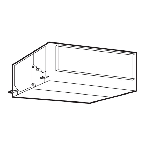
Marking of Positions of Suspension Bolts and Piping Connections (1) Mark the positions of the suspension bolts, refrigerant piping connections and drain connection. Unit: inch [mm] 52-3/8 [1330] (for Suspension Bolt) 50 [1270] 1-9/16 [40] 39-3/8 [1000] 5-7/16 [138] 56-φ1/8 [3] 1-15/16 [50] Around the Flange 2-9/16 x 1-3/8 [65 x 35]... - Page 15 (1) Prepare the suspension bolts, washers, nuts and vibration-proof rubbers, Retaining Nut Washer Vibration-proof Rubber Indoor Unit Vibration-proof Rubber Washer (2) Suspension Indoor Unit * Hook the suspension bracket to the nut, washer and vibration-proof rubber of each suspension bolt, as shown, starting at the opposite side and working over to the service cover side.
-
Page 16: Adjusting Of Unit Level
Adjusting of Unit Level (1) Use a level to verify that the unit is perfectly horizontal. There should be no degree of slope present. than the front side, to allow for proper drainage. (3) Tighten the bolts of the nuts with the suspension brackets after adjustment is completed. Adhesive must be applied to the bolts in order to prevent them from loosening. -
Page 17: Installation Of Remote Sensor
(12) The DOAS unit is designed to process outdoor air intake and should not be used as a standard indoor unit. If the internal load is higher, additional indoor units need to be added. (13) The DOAS unit is designed to intake outdoor air only. Indoor air is not recommended to be returned to the DOAS unit. -
Page 18: Installation Of Wired Controller (Optional Parts)
Installation of Wired Controller (Optional Parts) Refer to “Installation & Maintenance Manual” of optional wired controller. Setting of Wired Controller and Remote Sensor When the function of Indoor Temperature Control is set, a remote thermistor built in optional wired controller or remote sensor is necessary. -
Page 19: Refrigerant Piping Work
Refrigerant Piping Work Piping Materials (1) The tolerance of refrigerant piping length differs depending on the combination with the outdoor unit. Refer to “Installation and Maintenance Manual” of the outdoor unit for details. (2) Select the piping size from the following table. Table 6.1 Piping Size inch (mm) Model... -
Page 20: Piping Connection
Piping Connection (1) Position of piping connection is shown below. Unit: inch [mm] Refrigerant Liquid Pipe Connection Refrigerant Gas Pipe Connection 2-7/8 [72] (Drain Pipe Connection) 9-15/16 [252] 4-15/16 [126] (Refrigerant Gas and Liquid Pipe Connection) 13-5/8 [346] 18-7/16 [469] Drain Pipe Connection VP25 (Outer Diameter φ1-1/4 [32]) Release the gas before removing... - Page 21 (3) After brazing, insulate the pipes after checking that there is no leakage. At that time, be sure to cover the space between two insulating piece by insulation pipe (factory-supplied accessory). Thermal Insulation Pipe Thermal Insulation (Accessory) Pull Liquid Pipe Indoor Unit Gas Pipe Thermal Insulation...
-
Page 22: Drain Piping
Drain Piping Do not put the drain pipe for the indoor unit into the drainage trench where corrosive gases occur. NOTICE to property damage. back into the unit and it may cause the water leakage when the unit operation is stopped. unit must be higher than the common pipe. - Page 23 NOTICE following procedure. a. Turn ON the power supply. b. Pour 68 to 84oz (2 to 2.5 liters) of water into the drain pan. the end of the drain piping, check for leaks in main drain line if none are found repeat test until water is observed at end of main drain line.
-
Page 24: Electrical Wiring
Electrical Wiring Do not open the service cover or access panel for the indoor or outdoor units without turning OFF the main power supply. It can result in an electrical shock. Tighten screws according to the following torque. moisture and insects. Run the electrical wiring through the connecting hole in the side cover when using conduit. -
Page 25: Electrical Wiring Capacity
Electrical Wiring Capacity requirements. The equipment installer is responsible for understanding and abiding by applicable codes Do not operate the system until all the check points have been cleared. (A) Verify that electrical resistance is more than one megaohm by measuring the resistance between ground and the terminals of the various electrical components. - Page 26 Table 8.1 Recommended Wiring Capacity and Size Minimum Wire Thickness Main Switch [AWG (mm Circuit Interrupter> <Minimum Power Circuit Model Nominal Power Supply Nominal Nominal Ground Ampacity> Sensitive Supply Communication Current Current Wiring Current Wiring Size Cable Size Size <Main> [mA] (H,Y)DOA096B21S 18 (0.82) 18 (0.82)
-
Page 27: Position Of Electrical Wiring Connection
Position of Electrical Wiring Connection • The electrical wiring connection for the indoor unit is shown in Section 8.2.2. unit for the combination before the wiring work. The screws at the terminal block should be performed according to the tightening torque as shown in the table below. Tightening Torque for Terminals Screw Size Tightening Torque... - Page 28 (1) Connect the cable for the optional controller or the optional extension cable to the terminals inside the electrical box through the connecting hole of the cabinet. (2) Connect the power supply and the ground wiring to the terminals in the electrical box. (3) Connect the cables between the indoor unit and the outdoor unit to the terminals inside the electrical box.
- Page 29 (10) Wired Controller Connection (a) Wired Controllers at each unit for individual operation setting DOAS DOAS Unit Unit Outdoor Unit Wired Wired Controller Controller NOTE: DOAS unit must be operated with single wired controller only. (b) Wired Controller connections between different refrigerant systems DOAS Standard Standard...
- Page 30 < Caution for Electrical Wiring > Indoor Unit Indoor Unit Indoor Unit Indoor Unit Indoor Unit Indoor Unit Switchbox P00860Q-rev.2...
-
Page 31: Wiring Connection
Wiring Connection (1) Remove the connecting hole cover of the electrical box and install the rubber bush (Accessory) to the connecting hole for communication cable. (2) Pass the communication cable and the wired controller cable through the connecting hole for communication cable. - Page 32 Produced in 2018 or later Electrical control box cover with cut-out panel Unit: inch [mm] Electrical Control Box For Power Supply Wiring For Communication Cable 6-15/16 [177] φ1-1/8 [27.8] Wiring Hole with Rubber Bush 8-9/16 [217] φ1-1/8 [27.8] Wiring Hole for Conduit Tube Cord Clamp PVC Tube (Accessory) Cord Clamp...
-
Page 33: Dip Switches Setting
DIP Switches Setting Otherwise, the setting will be invalidated and not take effect. (2) Positions of DIP switches are shown below. (3) Unit No. Setting (RSW1 & DSW6) Setting is not required. Unit No. Setting Indoor unit numbers are set by the auto-address DSW6 (Tens Digit) RSW1 (Units Digit) Ex.) Set at No.16 Unit... - Page 34 (6) Refrigerant Cycle No. Setting (RSW2 & DSW5) Refrigerant Cycle No. Setting This setting is required. The unit arrives with all DSW5 (Tens Digit) RSW2 (Units Digit) Ex.) Set at No.5 Cycle DSW5 Setting Set by inserting Position slotted screwdriver into the groove.
-
Page 35: Setting Of Control Mode
Setting of Control Mode The following procedure shows the setting by CIW01. The Indoor Temperature Control mode has been set at factory. It can be changed to Outlet Air Temperature mode, so comply with the following instructions according to the installation conditions and purposes. And the settings are necessary for both the indoor and outdoor unit. - Page 36 Test Run Menu for at least three seconds during the normal mode Test Run (when unit is not operated). The Test Run menu will be displayed. Function Selection Thermistor Selection Input/Output press “OK”. Elevating Grille Setting Sel. Entr Back Rtrn 3.
-
Page 37: Setting By Dsw8 (Control Mode) On Pcb
8.7.3 Setting by DSW8 (Control Mode) on PCB (1) Remove the electrical box cover according to Section 8 “Electrical Wiring”, and Section 8.4 “Wiring Connection”. Refer to Section 8.5 ”DIP Switches Setting” for the location of DSW8 (Control Mode). (2) Set DSW8 (Control Mode) on PCB according to the installation conditions and purposes, following the DSW8 (Control Mode Setting) Indoor Temperature Control Outlet Air Temperature Control... -
Page 38: Setting Of Outdoor Unit
8.7.5 Setting of Outdoor Unit The applicable outdoor units of this setting are as below. < Applicable Outdoor Units > Type Model (H,Y)VAHP_B(3,4)1S unit. 7-Segment Display Setting Item Contents SEG2 SEG1 Initial Setting Outlet Air Temperature Control for DOAS Outlet Air Temperature Control NOTE: The setting should be performed during the outdoor unit stoppage. -
Page 39: Test Run
Before Test Run Verify that there are no problems with the installation, and do not perform Test Run until all the following conditions have been resolved. from the outdoor unit. Verify that refrigerant piping and the communication cable are connected to the same refrigerant cycle system. - Page 40 address function is not performing correctly due to incorrect wiring or electrical interference. Turn The power supply to the indoor unit is not turned ON or there is an incorrect wiring issue. Incorrect connection of the interconnecting cable between indoor units or a poorly connected controller cable.
-
Page 41: Alarm Code
Alarm Code Alarm (Troubleshooting) Code Table Code Category Nature of Problem Likely Cause Activation of a protection device Indoor Unit the drain pan.) A problem exists in the piping. Activation of protection device; High Pressure Cut; (R410A: 601 psi (4.15MPa)), fan Outdoor Unit (Except for Alarm Code: 41, 42) motor lockup during the outdoor unit cooling operation. - Page 42 © 2016 Johnson Controls, Inc. P00860Q-rev.2 Code No. LIT-12012220 Revised February 2018...
Need help?
Do you have a question about the YDOA096B21S and is the answer not in the manual?
Questions and answers