Durr Dental VistaScan Mini View Installation And Operating Instructions Manual
Hide thumbs
Also See for VistaScan Mini View:
- Installation and operating instructions manual (64 pages) ,
- Installation and configuration instructions (4 pages) ,
- Installation and operating instructions manual (52 pages)

Subscribe to Our Youtube Channel
Related Manuals for Durr Dental VistaScan Mini View


Summary of Contents for Durr Dental VistaScan Mini View
- Page 1 VistaScan Mini View Installation and Operating Instructions 2142100002L02 ...
-
Page 3: Table Of Contents
Contents 6.1 Installation/setup room ..16 6.2 System requirements ... . 16 6.3 Monitor ..... . 16 Important information Installation . - Page 4 Contents Troubleshooting 14 Tips for operators and service techni- cians ......36 14.1 Poor X-ray image....36 14.2 Software error .
-
Page 5: Important Information
Important information About this document Other symbols These symbols are used in the document and These installation and operating instructions on or in the unit: form part of the unit. Note, e.g. specific instructions regarding If the instructions and information in efficient and cost-effective use of the unit. -
Page 6: Safety
2.1 Intended purpose of the X-ray image on the touch screen is not suitable for the purposes of diagnosis. VistaScan Mini View The unit is intended exclusively for use in dental 2.4 General safety information applications for the scanning and processing of image data on an image plate. -
Page 7: Only Use Genuine Parts
Important information Observe the EMC rules concerning medical Image plate devices The image plate contains barium compounds. Observe specific precautionary measures re- Dispose of the image plate properly in accord- lating to electromagnetic compatibility (EMC) ance with the locally applicable regulations. for medical devices, see "18 Information In Europe, dispose of the image plate in ac- about EMC in accordance with EN 60601-1-... -
Page 8: Product Description
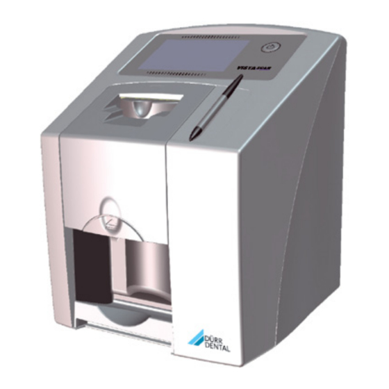
Product description Overview VistaScan Mini View image plate scanner Stylus Image plate intraoral Light protection cover intraoral Storage box SDHC memory card (fitted in the unit) DBSWIN imaging software DVD VistaSoft imaging software DVD Power supply unit with country-specific adapter... -
Page 9: Scope Of Delivery
... . . 2142-71 Light Protection Cover Plus size 2 – VistaScan Mini View basic unit 3 x 4 cm (1000 pcs.) ... 2130-082-55 –... -
Page 10: Disposable Materials
Product description 3.4 Disposable materials The following materials are consumed during operation of the device and must be reordered separately: Cleaning and disinfection Image plate cleaning wipe (10 pcs.) ....CCB351B1001 FD 350 Classic disinfection wipes . -
Page 11: Technical Data
Product description Technical data 4.1 Image plate scanner Electrical data for the unit Voltage V DC Max. current consumption 1.25 Output < 30 Type of protection IP20 Electrical data for the power supply unit Voltage V AC 100 - 240 Frequency 50 - 60 Protection class... -
Page 12: Image Plate
Product description Network connection Connector RJ45 Type of connection Auto MDI-X ≥ CAT5 Cable type WLAN connection WLAN technology 802.11b/g Encryption WPA, WPA2 Memory card Type SDHC Maximum memory capacity File system FAT32 ≥ 4 Performance class Class Ambient conditions during operation Temperature °C +10 to +35... -
Page 13: Light Protection Cover
Product description 4.3 Light protection cover Classification Medical Devices Directive (93/42/EU) Class I 2142100002L02 1611V004... -
Page 14: Type Plate
Product description Operation 4.4 Type plate The type plate is located on the rear of the unit. 5.1 Image plate scanner REF Order number Serial number 4.5 Conformity assessment This device has been subjected to conformity acceptance testing in accordance with the cur- rent relevant European Union guidelines. -
Page 15: Image Plate
Product description After scanning, the image plate runs through the unit manages the X-ray jobs in a waiting list from erasure unit. Image data still held on the image which the required X-ray job can be selected plate is erased with the aid of bright light. using the touch screen and then executed. -
Page 16: Light Protection Cover
Product description 5.3 Light protection cover The light protection cover provides several pro- tective functions for the intraoral image plate: – Protection against sunlight and UV light, and therefore protection against accidental erasure – Protection against mechanical damage – Protection against contamination and soiling Marker The light protection cover is a disposable item. -
Page 17: Bite Protector (Optional)
Product description 5.7 Bite protector (optional) The bite protector protects the image plate size 4 as well as the light protection cover against heavy mechanical damage, e.g. if the patient bites down too hard during the X-ray ex- posure. 2142100002L02 1611V004... -
Page 18: Installation/Setup Room
Installation Installation Only qualified specialists or employees trained by Dürr Dental are permitted to 7.1 Carrying the unit install, connect and start using the unit. Requirements NOTICE Risk of damage to sensitive compo- 6.1 Installation/setup room nents in the unit as a result of shocks The room chosen for set up should fulfil the fol- or vibrations lowing requirements:... -
Page 19: Removing The Protective Film From The Touch Screen
Installation Installing the unit with the wall mounting Check whether the memory card has been in- bracket serted in the unit correctly. If the memory card has been inserted in the unit incorrectly, take The unit can be mounted on a wall with the wall it out again and re-insert it properly. -
Page 20: Connecting The Unit To The Network
Installation 7.7 Connecting the unit to the net- Attach the matching country-specific adapter to the power supply unit. work Purpose of the network connection The network connection is used to exchange in- formation or control signals between the unit and a software installed on a computer, in order to, e. g.: –... -
Page 21: Commissioning And First Start-Up
Installation Commissioning and first Always comply with the relevant requirements from of IEC 60601-1-1 (EN 60601-1-1) when start-up connecting the unit to other appliances, e.g. to a computer system, both inside and out- side of the patient environment. NOTICE Only connect peripheral units (e.g. computer, Short circuit due to the build up of monitor, printer) that conform at least to the condensation... - Page 22 Installation Configuring WLAN on the unit Entering a fixed IP address (recommended) If the unit is to be operated via WLAN, the con- To reset the network settings, keep the nection to the unit needs to be configured. unit reset key pressed for 15 - 20 sec- onds while switching on.
- Page 23 Installation Select the unit from the Registered Devices Click list. Select the mode class. Select the mode. Click on Scan Image. Scan an image plate, see "11.2 Scanning the image data via a computer". Entering a fixed IP address (recommended) To reset the network settings, keep the unit reset key pressed for 15 - 20 sec- onds while switching on.
-
Page 24: X-Ray Unit Settings
Installation 8.2 X-ray unit settings Intraoral X-ray units If 60 kV can be set on the X-ray unit, this setting is preferred. The standard exposure values for F-speed film (e. g. Kodak Insight) can be used. The following table shows the standard values for the exposure time and the dose area product of an image plate for an adult patient. -
Page 25: Acceptance Tests
Installation DC emitter, 6 mA Tube length 30 cm Without X-ray field X-ray field limitation X-ray field limitation limitation 70 kV mGycm 70 kV mGycm 70 kV mGycm Incisors 0.08 s 0.08 s 0.08 s Premolars 0.11 s 10.0 0.11 s 0.11 s Molars 0.14 s... -
Page 26: Operation
Operation Operating the touch screen NOTICE Damage to the touch screen due to incorrect handling Only operate the touch screen using your fingertips or the stylus. Do not use a sharp instrument (e.g. Select a command. ballpoint pen) to operate the touch screen. -
Page 27: Calling Up Messages On The Touch Screen
Operation 10 Correct use of image 9.4 Calling up messages on the touch screen plates The Messages view shows an overview of all previous messages. Here, the messages are di- CAUTION vided into the following categories: Image plates are toxic Image plates that are not packed in a Fault Unit will no longer func-... -
Page 28: Operation
Operation 11 Operation Protect the image plates against sunlight and ultraviolet light. Store image plates in a light protection cover CAUTION or foil cassette of the correct size. The image data on the image plate is Image plates will be pre-exposed on exposure not permanent. - Page 29 Operation Completely slide the image plate into the light In the case of image plates Plus size 4, place protection cover. The black (inactive) side of the bite protector around the light protection the image plate must be visible. cover with image plate if necessary. Taking the X-ray NOTICE Damage to the image plate caused...
-
Page 30: Scanning The Image Data Via A Computer
Operation Tear off the light protection cover. WARNING Contamination of the unit Clean and disinfect the light protec- tion cover before removing the image plate. In the event of heavy soiling, e.g. from blood, dry clean the light protection cover and pro- tective gloves, e.g. wipe with a clean cellulose cloth. -
Page 31: Scanning Image Data Via The Touch Screen On The Unit
Operation The light protection cover is held in place by the fixing mechanism and is not transported into the unit. Scanning progress is displayed on the touch screen. The image data is automatically transmitted to the imaging software. After it has been scanned, the image plate is erased and drops into the collection tray. - Page 32 Operation Scanning: The touch screen will display an animated visual symbol requesting insertion of the im- Before scanning the image data, the age plate. patient data and exposure settings of the image are entered and then saved Only insert the image plate when the with the image data.
-
Page 33: Erasing The Image Plate
Operation Slide the image plate out of its light protection Transmitting image data to the computer cover downwards into the unit until the image X-ray images generated via the touch screen on plate is automatically drawn in. the unit are saved to the SD card. These X-ray images can be imported to the imaging software via a network connection (e.g. -
Page 34: Cleaning And Disinfection
Operation 12 Cleaning and disinfection Use of a protective cover The protective cover protects the unit against Use the following cleaning and disinfectant dirt and dust during extended periods in which it agents: is not used. – FD 322 rapid surface disinfectant WARNING –... -
Page 35: Light Protection Cover
Operation Clean the cover, fixing mechanism and inside NOTICE parts with a moist, soft, lint-free cloth. Heat can damage plastic parts. Do not use a thermal disinfectant or steam sterilizer on any parts of the unit. Touch on the touch screen. The fixing mechanism moves into the clean- ing position. -
Page 36: Stylus
Operation NOTICE Heat or humidity will damage the image plate. Do not steam sterilise the image plate. Do not immersion-disinfect the image plate. Only use approved cleaning agents. Soiling on both sides of the image plate should be cleaned off with a soft, lint-free cloth prior to every use. -
Page 37: Maintenance
Operation 13 Maintenance 13.1 Recommended maintenance schedule Only trained specialists or personnel trained by Dürr Dental may service the unit. Prior to working on the device or in case of danger, disconnect it from the mains (e. g. pull the mains plug). The recommended maintenance intervals are based on using the unit for 15 intraoral images per day and 220 working days per year. -
Page 38: Troubleshooting
Troubleshooting 14 Tips for operators and service technicians Any repairs above and beyond routine maintenance must only be carried out by suitably qualified personnel or by one of our service technicians. Prior to working on the device or in case of danger, disconnect it from the mains (e. g. pull the mains plug). - Page 39 Troubleshooting Fault Probable cause Solution Top or bottom bulge in the Image plate fed in off-centre and Check the error code on the X-ray image at an angle touch screen. Insert the image plate centrally and straight. Image plate exposed on the Insert the image plate correctly X-ray image is mirror- inverted...
- Page 40 Troubleshooting Fault Probable cause Solution Shadow on the X-ray im- Image plate removed from the Do not handle image plates light protection cover before without a light protection cover. scanning Store the image plate in a light protection cover. X-ray image cut off, part The metal part of the X-ray tube When taking an X-ray, make missing...
- Page 41 Troubleshooting Fault Probable cause Solution Horizontal, grey lines on Transport slipping Clean transport mechanism, the X-ray image, extending replace belts if necessary. beyond the left and right image edge X-ray image is stretched Incorrect light protection cover or Only use original accessories. image plate used lengthwise with bright, horizontal stripes...
-
Page 42: En 14.2 Software Error
Troubleshooting Fault Probable cause Solution Lamination of the image Incorrect retainer system used Only use original image plates plate becoming detached and film retainer systems. at the edge Image plate handled incorrectly. Use the image plate correctly. Observe the operating instruc- tions for the image plates and film retainer systems. -
Page 43: Fault On The Unit
Troubleshooting Fault Probable cause Solution The unit does not appear Unit is connected behind a router Configure the IP address without in the options list in Vista- an intermediate router on the Config unit. Reconnect the router. Manually enter the IP address in VistaConfig and register the unit. -
Page 44: Error Messages On The Touch Screen
Troubleshooting Fault Probable cause Solution Loud operating noises Radiation deflector defective Inform a service technician. after switching on lasting more than 30 seconds The unit has not yet completed After switching on, wait 20 - 30 Unit not responding the startup procedure seconds until the startup proce- dure has finished. - Page 45 Troubleshooting Fault Probable cause Solution Error code -1026 Incorrect acquisition mode Select a different acquisition mode Inform a service technician. Update the firmware. Reset the scanning modes to the factory settings via the unit interface or the Imaging Software. Error code 1100 Permitted time for scan process Inform a service technician.
- Page 46 Troubleshooting Fault Probable cause Solution Error code 10015 Image plate fed in off-centre Insert the image plate centrally. Error code 10017 Unit shutting down Wait until the unit has shut down completely. System error during startup of the Switch the unit off and back on Error code 2 unit again.
-
Page 47: Appendix
Appendix 15 Settings menu layout Unit information Unit data Dealer information Report Access level User Administrator Service Technician Factory Technician System settings Language German (DE) English (EN) Date & time Date Time Network MAC address Name Interface WLAN DHCP IP address Subnet mask Gateway Settings for image ac-... - Page 48 Appendix Service menu Test Scanning modes Edit scanning modes Display scanning modes Maintenance Firmware update Reset maintenance in- terval Diagnosis Statistics Manipulation Transport settings Service mode Sensors Oscilloscope Check touch screen Display test images Messages Factory settings Visible from access level Operator or higher Visible from access level Administrator or higher Visible from access level Service Technician or higher 2142100002L02 1611V004...
-
Page 49: Scanning Times
Appendix 16 Scanning times The scanning time corresponds to the time taken for complete scanning of image data and depends on image plate format and pixel size. The time to image will depend largely on the computer system used and its work load. Times stated are approximate. -
Page 50: File Sizes (Uncompressed)
Appendix 17 File sizes (uncompressed) The actual file size will depend on the image plate format and the pixel size. File sizes stated are ap- proximate and have been rounded upwards. Suitable compression methods can considerably reduce the file size without loss of data. Theoretical resolution (LP/ Pixel size (μm) 12.5... -
Page 51: Information About Emc In Accordance With En 60601-1-2
Appendix 18 Information about EMC in accordance with EN 60601-1-2 18.1 General information The information in this leaflet includes excerpts from the relevant European standards for electrical, medical devices. It must be observed when installing Dürr Dental devices or combining them with products of other manufacturers. - Page 52 Appendix Resistance to electromagnetic interference (immunity) for all devices and systems The device is designed for use in electromagnetic environments specified below. The customer or operator of the device should ensure that the device is operated such an environment. Interference im- IEC 60601 - test Compliance level Electromagnetic environment...
- Page 53 Appendix Electromagnetic interference immunity for devices or systems that are not life-sustaining Portable and mobile communication devices should not be used any closer to the unit (including cables) than the recommended safety distance, which is calculated based on the applicable formula for the transmission frequency.
- Page 54 Appendix Recommended safety distance between portable and mobile HF communication devices and the unit The device is designed for use in the electromagnetic environments specified below, in which the HF disturbance variables are controlled. The customer or the operator of the device can help to prevent electromagnetic interference by maintaining the minimum distances between mobile HF communica- tion equipment (transmitters) and the device as recommended below in accordance with the maxi- mum output line of the communication equipment.
- Page 56 Dürr Dental aG Höpfigheimer Strasse 17 74321 Bietigheim-Bissingen Germany Fon: +49 7142 705-0 www.duerrdental.com info@duerr.de...
Need help?
Do you have a question about the VistaScan Mini View and is the answer not in the manual?
Questions and answers