Table of Contents
Advertisement
Quick Links
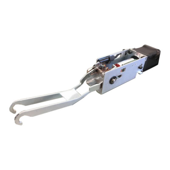
M L P - U L- M K I T
The Command Access MLP-UL-M-KIT is a field installable motorized latch-pullback kit for the
A.
E.
D.
Ki t In cl u de s
A.
1- Motor Mount w/ MM4S series module
B.
2- 8/32 X 1/4" Phillips head screws
C.
1- 8' Lead w/ VD Connector
D.
1- Push & go connector
E.
1- MM4S switch program sticker
F.
1- Dogging Hole Cap
C o m m a n d A c c e s s T e c h n o l o g i e s | 2 2 9 0 1 L a P a l m a A v e , Y o r b a L i n d a , C A 9 2 8 8 7 | P h o n e : ( 8 8 8 ) 6 2 2 - 2 3 7 7
INSERT Instructions
MARKS 8800 & 9900 series devices.
E.
F.
Cordless Drill
Hammer & Pin Punch(recommend) or 3/16 drill bit
5/16 Nut driver (recommended) or Flat head screwdriver
#2 Phillips head screwdriver
B.
G.
To o l s R e q ui r e d
C.
I
V
nstall
Ideo
# 2 0 0 9 4 _ I
Advertisement
Table of Contents

Related Manuals for Command access MLP-UL-M KIT


Summary of Contents for Command access MLP-UL-M KIT
- Page 1 M L P - U L- M K I T INSERT Instructions The Command Access MLP-UL-M-KIT is a field installable motorized latch-pullback kit for the MARKS 8800 & 9900 series devices. Ki t In cl u de s To o l s R e q ui r e d...
- Page 2 Technical Information MM4s V Ideo SPECIFICATIONS mm4s switches Low Torque Mode • Input Voltage: 24VDC +/- 10% Average Latch Retraction Current: 600 mA LOW TORQUE Average Holding Current: 150 mA • Wire gauge: Minimum 18 gauge STANDARD TORQUE Standard Torque Mode HIGH TORQUE •...
- Page 3 WIRE ACCESS WIRE RELEASE R ecommend ed Po w er Su ppli e s: All Command Access exit devices & field installable kits have been thoroughly cycle tested with Command Access power supplies at our factory. For more information click here or go to our website U S C U S T O M E R S U P P O R T 1 - 8 8 8 - 6 2 2 - 2 3 7 7 | W W W .
- Page 4 Installation Instructions Remove End Cap & Filler Plate Remove (4) screws from baserail Partially slide push pad off approx. 2-3” Using 5/32” drill bit. Open up the (2) back screw holes #3 & 4. Continue sliding push pad half way out of the base rail so activating bracket is accessible. Next, remove metal rod and AB mount can be put aside.
- Page 5 CONTINUED Attach the link assembly to the end of the activating bracket. Next, Secure link assembly to activating bracket place activating bracket into center of the motor mount. with Hex wrench provided. Link Assembly Re-install metal rod securing activating bracket to motor mount. Slide push pad with motor kit back into the device.
- Page 6 CONTINUED Re-install original screws in holes 1 & 2. Install new screws Connect your VD 8’ lead (CAT or VD retrofit) or you can provided in holes 3 & 4. remove the VD connector to hardwire- take stripped wire end and push into the push & go connector Next, plug in the push &...
Need help?
Do you have a question about the MLP-UL-M KIT and is the answer not in the manual?
Questions and answers