Table of Contents
Advertisement
P D 1 0 - U L- M K I T
INSERT Instructions
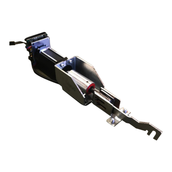
The PD10-UL-M-KIT is a field installable motorized latch pullback for the PD10/11, Doromatic or Falcon
A.
C.
Ki t In cl u de s
A.
Motor Mount w/MM4S
B.
1- 8' Lead w/ VD Connector
C.
2 - Sets of finished phillips screws
D.
MM4S Programming sticker
C o m m a n d A c c e s s T e c h n o l o g i e s | 2 2 9 0 1 L a P a l m a A v e , Y o r b a L i n d a , C A 9 2 8 8 7 | P h o n e : ( 8 8 8 ) 6 2 2 - 2 3 7 7
1690/1790, & First Choice 3600/3700.
B.
D.
To o l s R e q ui r e d
Cordless Drill or Phillips Screwdriver
Hacksaw
Advertisement
Table of Contents

Related Manuals for Command access PD10-UL-M Kit


Summary of Contents for Command access PD10-UL-M Kit
- Page 1 P D 1 0 - U L- M K I T INSERT Instructions The PD10-UL-M-KIT is a field installable motorized latch pullback for the PD10/11, Doromatic or Falcon 1690/1790, & First Choice 3600/3700. Ki t In cl u de s To o l s R e q ui r e d Motor Mount w/MM4S Cordless Drill or Phillips Screwdriver...
-
Page 2: Technical Information
Technical Information mm4s switches LOW TORQUE Low Torque Mode STANDARD TORQUE SPECIFICATIONS Average Latch Retraction Current: 600 mA HIGH TORQUE Average Holding Current: 150 mA PTS PROGRAMMING LOCKED Standard Torque Mode • Input Voltage: 24VDC +/- 10% Average Latch Retraction Current: 1 amp Average Holding Current: 215 mA •... -
Page 3: Installation Example
Optional Placement Reco mm end ed Pow e r S u p pl ies : All Command Access exit devices & field installable kits have been thoroughly cycle tested with Command Access power supplies at our factory. For more information, visit our website... - Page 4 Installation Instructions Remove HEAD COVER REMOVE FRONT AND BACK END CAPS Note: For AHT4/5 & PD11’s purchased after 2015 only. SLIDE PUSH PAD OFF DEVICE REMOVE BASERAIL ASSEMBLY FIRST BY REMOVING 4 SCREWS REMOVE BOTH SCREWS ATTACHING HEAD ASSEMBLY TO HOUSING REMOVE DOGGING ASSEMBLY AND BACK ACTIVATING BRACKET SCREWS.
- Page 5 Installation Instructions REMOVE DOGGING ASSEMBLY FROM BASE RAIL Remove ASSEMBLY FROM BASE RAIL AND REMOVE TOP ROLLER PINS Remove pin from connecting rod for RIM. For CVR skip CVR - Remove connecting rod assembly by pulling this step. away from device housing. Confirm which back activating bracket you have and follow below guide.
-
Page 6: Installing The Kit
ONCE YOUR BRACKETS ARE PUT BACK IN LINE, IT’S TIME TO LINE UP HOOK ACTIVATING ARM OVER BOTTOM PIN OF BACK ACTIVATING YOUR PD10-UL-M KIT.SLIDE KIT INTO REAR OF BAR. BRACKET U S C U S T O M E R S U P P O R T 1 - 8 8 8 - 6 2 2 - 2 3 7 7 | W W W . C O M M A N D A C C E S S . C O M | C A C U S T O M E R S U P P O R T 1 - 8 5 5 - 8 2 3 - 3 0 0 2... -
Page 7: Reassembling The Device
Installation Instructions INSTALL MOUNTING SCREWS. TEST MECHANICALLY PULL KIT BACK/LINE UP DOGGING HOLES ON BACK OF DEVICE WITH MOUNTNG HOLES. REASSEMBLING THE DEVICE MAKE SURE FLAP IS UP ON ACTIVATING BRACKET IF RIGGING OR BINDING SLIDE PUSH PAD ON MAKING SURE THAT THE SIDES FIT INTO THE CORRECT GROOVES RE-INSERT TOP PINS AND PUSH PAD U S C U S T O M E R S U P P O R T 1 - 8 8 8 - 6 2 2 - 2 3 7 7 | W W W . - Page 8 Installation Instructions TEST DEVICE. Add sticker to back of device RE-INSTALL END CAPS Setting PTS **Important Info** Make sure to set PTS before finishing installation Step 1- Select your preferred torque mode (ships in standard torque) Press the device push pad to the desired setting.
- Page 9 Installation Instructions Add program sticker to back of the device. Setting PTS Step 1- Select your preferred torque mode (ships in standard torque) Press the device push pad to the desired setting. (Recommend to fully depress and release 5%, giving the device room for changing door conditions.) Step 2- While depressing the push pad, apply power.
Need help?
Do you have a question about the PD10-UL-M Kit and is the answer not in the manual?
Questions and answers