Advertisement
CY L P - U L- M K I T
The Command Access CYLP-UL-M-KIT is a field-installable motorized latch-pullback kit for the Corbin
A.
E.
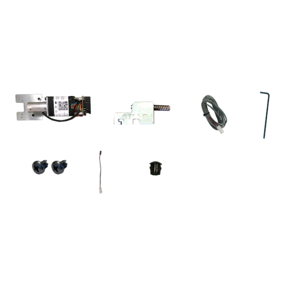
Ki t In cl u de s
A.
1- Motor Mount w/ MM4S series module
B.
1 - Attaching Magnet Bracket
1- 8' Lead w/ VD Connector
C.
1 - 1/16" Allen Wrench
D.
2- Phillips head screws
E.
1- Push & Go Pigtail
F.
1- Dogging Hole Cap
G.
U S c u s t o m e r s u p p o r t 1 - 8 8 8 - 6 2 2 - 2 3 7 7 | w w w . c o m m a n d a c c e s s . c o m | C A c u s t o m e r s u p p o r t 1 - 8 5 5 - 8 2 3 - 3 0 0 2
INSERT Instructions
4000/5000 & Yale 7000 series devices.
B.
F.
G.
C.
To o l s R e q ui r e d
Cordless Drill
#2 Phillips head screwdriver
D.
INSTALL VIDEO
1
# 2 0 0 9 2 _ F
Advertisement
Table of Contents

Related Manuals for Command access CYLP-UL-M KIT


Summary of Contents for Command access CYLP-UL-M KIT
- Page 1 CY L P - U L- M K I T INSERT Instructions The Command Access CYLP-UL-M-KIT is a field-installable motorized latch-pullback kit for the Corbin 4000/5000 & Yale 7000 series devices. Ki t In cl u de s To o l s R e q ui r e d...
- Page 2 Technical Information MM4S VIDEO SPECIFICATIONS mm4s switches • Input Voltage: 24VDC +/- 10% STANDARD TORQUE • Wire gauge: Minimum 18 gauge Standard Torque Mode HIGH TORQUE • Direct wire run - no relays or access control Average Latch Retraction Current: 1 Amp PTS PROGRAMMING on Average Holding Current: 215 mA units in-between power supply &...
- Page 3 WIRE ACCESS WIRE RELEASE R eco mmend ed Po we r S uppl i es : All Command Access exit devices & field installable kits have been thoroughly cycle tested with Command Access power supplies at our factory. For more information...
- Page 4 Installation Instructions If dogging assembly is present, remove (2) Slide off Filler plate. screws and discard dogging assembly. Install attaching bracket to the rod on the bottom Refer to this picture for the next 2 steps. of the back activating bracket. Use the 2nd set screw to set the height of the Using the 1/16”...
- Page 5 Installation Instructions Continue feeding the acme thread until the holes on Slide the motor mount into the device. Feed the the motor mount line up to the existing dogging holes. acme thread into the cylinder clockwise. Next, install the (2) screws provided. Cylindrical housing Connect your 8’...
Need help?
Do you have a question about the CYLP-UL-M KIT and is the answer not in the manual?
Questions and answers