Sign In
Upload
Manuals
Brands
Pfeiffer Vacuum Manuals
Water Pump
HiPace 300 P
Pfeiffer Vacuum HiPace 300 P Manuals
Manuals and User Guides for Pfeiffer Vacuum HiPace 300 P. We have
2
Pfeiffer Vacuum HiPace 300 P manuals available for free PDF download: Operating Instructions Manual
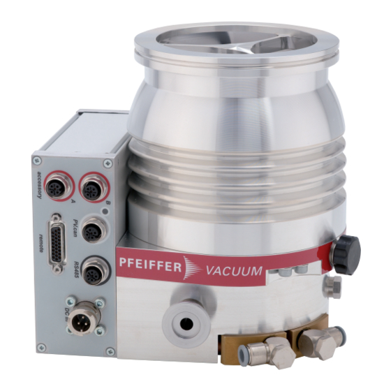
Pfeiffer Vacuum HiPace 300 P Operating Instructions Manual (64 pages)
Turbopump
Brand:
Pfeiffer Vacuum
| Category:
Water Pump
| Size: 10 MB
Table of Contents
Table of Contents
3
About this Manual
7
Validity
7
Related Documents
7
Variants
7
Target Group
7
Conventions
7
Instructions in the Text
7
Pictographs
8
Stickers on the Product
8
Fig. 2: Position of the Stickers on the Product
8
Abbreviations
9
Trademark Proof
9
Safety
10
General Safety Information
10
Safety Instructions
10
Safety Precautions
14
Limits of Use of the Product
15
Proper Use
15
Foreseeable Improper Use
15
Tbl. 2: Permissible Ambient Conditions
15
Personnel Qualification
16
Ensuring Personnel Qualification
16
Personnel Qualification for Maintenance and Repair
17
Advanced Training with Pfeiffer Vacuum
17
Product Description
18
Function
18
Cooling
18
Rotor Bearing
18
Fig. 3: Design 300 P (Example DN 100 ISO-K and DN 100 CF-F)
18
Drive
19
Shipment
19
Identifying the Product
19
Product Types
19
Product Features
19
Transportation and Storage
20
Transport
20
Storage
20
Installation
21
Preparatory Work
21
Connecting the High Vacuum Side
21
Requirements for the Dimensioning of a Counter Flange
21
Considering Earthquake Protection
22
Tbl. 5: Requirements for the Dimensioning of Customer-Specific High Vacuum con
22
Using a Splinter Shield or Protective Screen
23
Using the Vibration Compensator
23
Tbl. 6: Reduction of the Pumping Speed When Using a Splinter Shield or Protective
23
Fig. 4: Example: Safety Connections
23
Mounting Orientations
24
Attaching ISO-K Flange Onto ISO-K
24
Attaching ISO-K Flange to ISO-F
24
Fig. 5: Recommended Alignment When Using Oil-Sealed Backing Pumps
24
Fig. 6: Flange Connection ISO-K to ISO-F, Bracket Screws
24
Fig. 7: Flange Connection ISO-K with ISO-F, Hexagon Head Screw and Tapped Hole
25
Fig. 8: Flange Connection ISO-K with ISO-F, Stud Screw and Tapped Hole
25
Attaching ISO-F Flange to ISO-F
26
Fig. 9: Flange Connection ISO-K with ISO-F, Stud Screw and through Hole
26
Fig. 10: Flange Connection ISO-F, Hexagon Head Screw and Tapped Hole
26
Fig. 11: Flange Connection ISO-F, Stud Screw and Tapped Hole
26
Attaching CF Flange to CF-F
27
Fig. 12: Flange Connection ISO-F, Stud Screw and through Hole
27
Fig. 13: Flange Connection CF-F, Hexagon Head Screw and through Hole
27
Fig. 14: Flange Connection CF-F, Stud Screw and Tapped Hole
28
Fig. 15: Flange Connection CF-F, Stud Screw and through Hole
28
Connecting the Fore-Vacuum Side
29
Cooling Water Connection
29
Fig. 16: Example of Fore-Vacuum Connection on Hipace 300
29
Tbl. 7: Requirements on the Cooling Water Composition
30
Tbl. 8: Requirements on the Cooling Water Connection
30
Connecting Accessories
31
Fig. 17: Connecting the Cooling Water Supply
31
Connecting the Electrical Supply
32
Earthing the Turbopump
32
Establishing the Electric Connection
33
Fig. 18: Example: Connecting the Grounding Cable
33
Fig. 19: Connecting the Electronic Drive Unit to a Power Supply Pack
34
Operation
35
Commissioning
35
Tbl. 10: Factory Setting of the Electronic Drive Unit When Delivered
35
Operating Modes
36
Operation Without Operating Unit
36
Operation Via Multi-Function Connection "Remote
36
Operation Via Connection "E74
36
Operation Via Pfeiffer Vacuum Display and Control Unit
36
Operation Via Field Bus
36
Switching on the Turbopump
37
Operation Monitoring
37
Operating Mode Display Via LED
37
Temperature Monitoring
38
Switching off and Venting
38
Switching off
38
Venting
38
Tbl. 11: Behavior and Meaning of the Leds on the Electronic Drive Unit
38
Tbl. 12: Factory Settings for Delayed Venting in Turbopumps
39
Maintenance
40
General Maintenance Information
40
Checklist for Inspection and Maintenance
40
Replace Operating Fluid Reservoir
41
Tbl. 13: Maintenance Intervals
41
Removing the Operating Fluid Reservoir
42
Fig. 20: Removing the Operating Fluid Reservoir
42
Installing the Operating Fluid Reservoir
43
Fig. 21: Installing the Operating Fluid Reservoir
43
Replacing the Electronic Drive Unit
44
Removing Electronic Drive Unit
44
Installing the Electronic Drive Unit
45
Fig. 22: Removal of Electronic Drive Unit TC 400
45
Fig. 23: Installation of Electronic Drive Unit TC 400
45
Confirming the Speed Specification
46
Tbl. 14: Characteristic Nominal Rotation Speeds of the Turbopumps
46
Decommissioning
47
Shutting down for Longer Periods
47
Recommissioning
47
Recycling and Disposal
48
General Disposal Information
48
Dispose of Turbopumps
48
Malfunctions
49
Tbl. 15: Troubleshooting Turbopumps
50
Service Solutions by Pfeiffer Vacuum
51
Spare Parts Hipace 300 P
53
Fig. 24: Spare Parts Hipace 300 P
53
Accessories
54
Technical Data and Dimensions
55
General
55
Technical Data
55
Substances in Contact with the Media
58
Dimensions
58
Fig. 25: Hipace 300 | TC 400 | DN 100 ISO-K
59
Fig. 26: Hipace 300 | TC 400 | DN 100 ISO-F
59
Fig. 27: Hipace 300 | TC 400 |DN 100 CF-F
59
Declaration of Conformity
60
Advertisement
Pfeiffer Vacuum HiPace 300 P Operating Instructions Manual (60 pages)
Turbo Pump
Brand:
Pfeiffer Vacuum
| Category:
Water Pump
| Size: 8 MB
Table of Contents
Table of Contents
3
1 About this Manual
7
Validity
7
Related Documents
7
Product Variants Affected
7
Target Group
7
Conventions
7
Instructions in the Text
7
Pictographs
8
Stickers on the Product
8
Abbreviations
9
Tbl. 1: Abbreviations Used in this Document
9
Fig. 2: Position of the Labels on the Product
9
2 Safety
10
General Safety Instructions
10
Safety Instructions
10
Safety Precautions
14
Limits of Use of the Product
14
Proper Use
15
Foreseeable Improper Use
15
Tbl. 2: Permissible Ambient Conditions
15
3 Product Description
17
Function
17
Cooling
17
Rotor Bearing
17
Fig. 3: Design 300 P (Example DN 100 ISO-K and DN 100 CF-F)
17
Drive
18
Shipment
18
Identifying the Product
18
Product Types
18
Product Features
18
4 Transportation and Storage
19
Transport
19
Storage
19
5 Installation
20
Preparatory Work
20
Connecting the High Vacuum Side
20
Requirements for the Dimensioning of a Counter Flange
20
Considering Earthquake Protection
21
Fig. 4: Example: Safety Connections
21
Using a Splinter Shield or Protective Screen
22
Using the Vibration Compensator
22
Mounting Orientations
22
Tbl. 6: Reduction of the Pumping Speed When Using a Splinter Shield or Protective Screen
22
Fig. 5: Recommended Alignment When Using Oil-Sealed Backing Pumps
22
Attaching ISO-K Flange Onto ISO-K
23
Attaching ISO-K Flange to ISO-F
23
Fig. 6: Flange Connection ISO-K to ISO-F, Bracket Screws
23
Fig. 7: Flange Connection ISO-K with ISO-F, Hexagon Head Screw and Tapped Hole
24
Fig. 8: Flange Connection ISO-K with ISO-F, Stud Screw and Tapped Hole
24
Fig. 9: Flange Connection ISO-K with ISO-F, Stud Screw and through Hole
24
Attach ISO-F Flange to ISO-F
25
Fig. 10: Flange Connection ISO-F, Hexagon Head Screw and Tapped Hole
25
Fig. 11: Flange Connection ISO-F, Stud Screw and Tapped Hole
25
Fastening CF Flange to CF-F
26
Fig. 12: Flange Connection ISO-F, Stud Screw and through Hole
26
Fig. 13: Flange Connection CF-F, Hexagon Head Screw and through Hole
26
Fig. 14: Flange Connection CF-F, Stud Screw and Tapped Hole
26
Connecting the Fore-Vacuum Side
27
Fig. 15: Flange Connection CF-F, Stud Screw and through Hole
27
Cooling Water Connection
28
Fig. 16: Example of Fore-Vacuum Connection on Hipace 300
28
Tbl. 7: Requirements on the Cooling Water Composition
29
Tbl. 8: Requirements on the Cooling Water Connection
29
Fig. 17: Connecting the Cooling Water Supply
29
Connecting Accessories
30
Connecting Accessories to the Turbopumps
30
Tbl. 9: Factory Pre-Set Accessory Connections on the Electronic Drive Unit
30
Connecting the Venting Valve
31
Connecting the Air Cooling
31
Fig. 18: Connecting the Air Cooling
31
Connecting Sealing Gas
32
Installing a Heating Jacket
32
Connecting the Electrical Supply
33
Fig. 19: Connection of the Heating Jacket
33
Earthing the Pump
34
Create Electrical Connection
34
Fig. 20: Example: Connecting the Grounding Cable
34
Fig. 21: Connecting the Electronic Drive Unit to a Power Supply Pack
35
6 Operation
36
Commissioning
36
Tbl. 11: Factory Setting of the Electronic Drive Unit When Delivered
36
Operating Modes
37
Operation Without Operating Unit
37
Operation Via Multi-Function Connection "Remote
37
Operation Via Connection "E74
37
Operation Via Pfeiffer Vacuum Display and Control Unit
37
Operation Via Field Bus
37
Switching on the Turbopump
38
Operation Monitoring
38
Operating Mode Display Via LED
38
Temperature Monitoring
39
Switching off and Venting
39
Switching off
39
Venting
40
Tbl. 13: Factory Settings for Delayed Venting of Turbopumps
40
7 Maintenance
41
General Maintenance Information
41
Maintenance Intervals and Responsibilities
41
Replacing the Operating Fluid Reservoir
41
Fig. 22: Removing the Operating Fluid Reservoir
42
Replacing the Electronic Drive Unit
43
Confirming the Rotation Speed Specification
44
Tbl. 14: Characteristic Nominal Rotation Speeds of the Turbopumps
44
Fig. 23: Installing and Removing the Electronic Drive Unit TC 400
44
8 Decommissioning
46
Shutting down for Longer Periods
46
Recommissioning
46
Disposing of the Vacuum Pump
47
9 Malfunctions
48
10 Service Solutions from Pfeiffer Vacuum
50
11 Spare Parts Hipace 300 P
52
Fig. 24: Spare Parts Hipace 300 P
52
12 Accessories
53
13 Technical Data and Dimensions
54
General
54
Technical Data
54
Tbl. 19: Technical Data for Hipace 300 P | 24 V
56
Tbl. 20: Technical Data for Hipace 300 P | 48 V
57
Dimensions
58
Fig. 25: Hipace 300 | TC 400 | DN 100 ISO-K
58
Fig. 26: Hipace 300 | TC 400 | DN 100 ISO-F
58
Fig. 27: Hipace 300 | TC 400 |DN 100 CF-F
58
Declaration of Conformity
59
Advertisement
Related Products
Pfeiffer Vacuum HiCube 30 Eco
Pfeiffer Vacuum HiCube 300 Eco
Pfeiffer Vacuum HiCube 300 Classic
Pfeiffer Vacuum HiCube 300 Pro
Pfeiffer Vacuum HiCube 300 H Pro
Pfeiffer Vacuum HIPACE 300 PLUS
Pfeiffer Vacuum HIPACE 30 NEO
Pfeiffer Vacuum DUO 35 C
Pfeiffer Vacuum DUO 35 MC
Pfeiffer Vacuum HIPACE 350
Pfeiffer Vacuum Categories
Water Pump
Control Unit
Measuring Instruments
Industrial Equipment
Security Sensors
More Pfeiffer Vacuum Manuals
Login
Sign In
OR
Sign in with Facebook
Sign in with Google
Upload manual
Upload from disk
Upload from URL