Advertisement
New Product
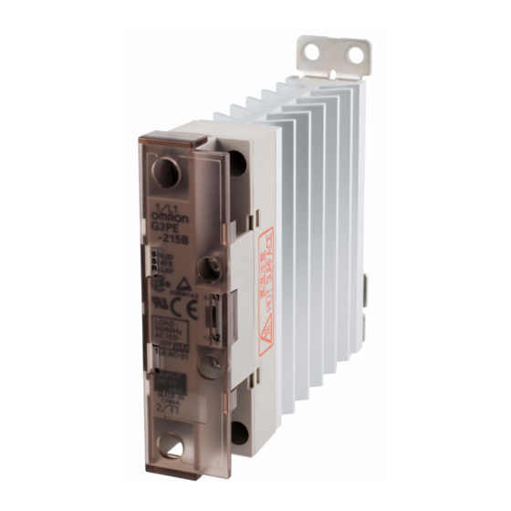
Solid State Relays for Heaters
Single-phase G3PE
Compact, Slim-profile SSRs with Heat
Sinks. Models with No Zero Cross for
a Wide Range of Applications.
• RoHS compliant.
• Models also available with no zero cross
• Improved surge dielectric strength for output circuits.
• Compact with a slim profile.
• Mount to DIN Track or with screws.
• Certification pending for UL, CSA, and EN (TÜV
certification).
Refer to Safety Precautions on page 18.
Ordering Information
List of Models
Number of
Isolation
phases
method
Phototriac
Single-phase
coupler
* The applicable load current depends on the ambient temperature. For details, refer to Load Current vs. Ambient Temperature in Engineering
Data on page 3.
Operation
Rated input
indicator
voltage
Yes (yellow)
12 to 24 VDC
Zero cross
Applicable load *
function
15 A, 100 to 240 VAC G3PE-215B DC12-24
25 A, 100 to 240 VAC G3PE-225B DC12-24
Yes
35 A, 100 to 240 VAC G3PE-235B DC12-24
45 A, 100 to 240 VAC G3PE-245B DC12-24
15 A, 100 to 240 VAC G3PE-215BL DC12-24
25 A, 100 to 240 VAC G3PE-225BL DC12-24
No
35 A, 100 to 240 VAC G3PE-235BL DC12-24
45 A, 100 to 240 VAC G3PE-245BL DC12-24
15 A, 200 to 480 VAC G3PE-515B DC12-24
25 A, 200 to 480 VAC G3PE-525B DC12-24
Yes
35 A, 200 to 480 VAC G3PE-535B DC12-24
45 A, 200 to 480 VAC G3PE-545B DC12-24
15 A, 200 to 480 VAC G3PE-515BL DC12-24
25 A, 200 to 480 VAC G3PE-525BL DC12-24
No
35 A, 200 to 480 VAC G3PE-535BL DC12-24
45 A, 200 to 480 VAC G3PE-545BL DC12-24
Model
1
Advertisement
Table of Contents

Related Manuals for Omron G3PE


Summary of Contents for Omron G3PE
-
Page 1: Ordering Information
35 A, 200 to 480 VAC G3PE-535BL DC12-24 45 A, 200 to 480 VAC G3PE-545BL DC12-24 * The applicable load current depends on the ambient temperature. For details, refer to Load Current vs. Ambient Temperature in Engineering Data on page 3. -
Page 2: Specifications
(at 400 VAC) (at 400 VAC) (at 400 VAC) (at 400 VAC) * The applicable load current depends on the ambient temperature. For details, refer to Load Current vs. Ambient Temperature in Engineering Data on page 3. Characteristics Model G3PE... -
Page 3: Engineering Data
−30 −20 Ambient temperature (°C) Ambient temperature (°C) Inrush Current Resistance: Non-repetitive Keep the inrush current to below the inrush current resistance value (i.e., below the broken line) if it occurs repetitively. G3PE-215B(L), G3PE-515B(L) G3PE-225B(L), G3PE-525B(L) G3PE-235B(L), G3PE-245B(L) G3PE-535B(L), G3PE-545B(L) - Page 4 Single-phase G3PE Close Mounting (3 or 8 SSRs) G3PE-215B(L) G3PE-225B(L) G3PE-235B(L) G3PE-245B(L) 3 Relays 3 Relays 3 Relays 3 Relays 8 Relays 8 Relays 8 Relays 8 Relays −40 −20 −40 −20 −40 −20 −40 −20 80 100 80 100...
-
Page 5: Solid State Relays
Single-phase G3PE Dimensions Note: All units are in millimeters unless otherwise indicated. Solid State Relays G3PE-215B(L) Two, ±0.2 4.6 dia. G3PE-225B(L) Two, M4 G3PE-515B(L) G3PE-525B(L) 100 max. ±0.2 Two, M3.5 Elliptical hole: 4.6 × 5.6 22.5 max. Note: Without terminal cover. -
Page 6: New Product
45 A, 200 to 480 VAC G3PE-545B-2 DC12-24 *1. The applicable load current depends on the ambient temperature. For details, refer to Load Current vs. Ambient Temperature in Engineering Data on page 10. *2. The applicable DIN Track is the TR35-15Fe (IEC 60715). For details, refer to the mounting information in the Safety Precautions. - Page 7 45 A, 200 to 480 VAC G3PE-545B-2H DC12-24 * The rated load current depends on the heat sink or radiator that is mounted. It also depends on the ambient temperature. For details, refer to Load Current vs. Ambient Temperature. Accessories (Order Separately) Heat Sink Heat resistance Rth (s-a) (°C/W)
- Page 8 Data on page 10. *2. Applicable Load Use the following formula to calculate the maximum total capacity of a heater load for a three-phase balanced load with delta connections. Maximum load capacity = Load current × Load voltage × √3 Example: 15 A ×...
-
Page 9: Heat Sinks
1.25 kg 1.65 kg 1.45 kg 2.0 kg 1.65 kg * The leakage current of phase S will be approximately √3 times larger if the 2-element model is used. Models with Externally Attached Heat Sinks Model G3PE- G3PE- G3PE- G3PE-... - Page 10 Three-phase G3PE Engineering Data Input Voltage vs. Input Impedance and Input Voltage vs. Input Current G3PE-2@@B-@@ G3PE-5@@B-@@ Ta = 25°C Input current Input current Input impedance Input impedance Input voltage (V) Input voltage (V) Load Current vs. Ambient Temperature Models with Built-in Heat Sinks...
- Page 11 Three-phase G3PE Inrush Current Resistance: Non-repetitive Keep the inrush current to below the inrush current resistance value (i.e., below the broken line) if it occurs repetitively. G3PE-215B-3(N)(H) G3PE-225B-3(N)(H), G3PE-525B-3(N)(H) G3PE-235B-3(N)(H), G3PE-535B-3(N)(H) G3PE-225B-2(N)(H), G3PE-525B-2(N)(H) G3PE-235B-2(N)(H), G3PE-535B-2(N)(H) G3PE-215B-2(N)(H) G3PE-515B-3(N)(H), G3PE-245B-3(N)(H), G3PE-545B-3(N)(H) G3PE-515B-2(N)(H),...
- Page 12 Three-phase G3PE Dimensions Note: All units are in millimeters unless otherwise indicated. Solid State Relays Models with Two, 4.6-dia. mounting holes Four, 8 dia. DIN Track Mounting Two, M3.5 G3PE-215B-3N G3PE-215B-2N 84.5 G3PE-225B-2N max. max. Two, R2.3 mounting G3PE-515B-3N holes...
-
Page 13: Din Track Mounting
Six, M5 80 max. 32.2 Note: Without terminal cover. Note: With terminal cover. Mounting Holes ±0.3 max. 23.2 19.1 120 max. ±0.3 Four, 4.5 dia. or M4 Terminal Arrangement/Internal Circuit Diagram G3PE-235B-3N G3PE-245B-2N G3PE-535B-3N G3PE-545B-2N L1/R L2/S L3/T L1/R L2/S L3/T... - Page 14 Two, M3.5 Six, M4 80 max. 4.6 × 5.6 elliptical hole 32.2 Note: With terminal cover. Note: Without terminal cover. DIN Track or screw mounting Mounting Holes Two, 4.5 dia. or M4 max. 23.2 19.1 ±0.3 55 max. Terminal Arrangement/Internal Circuit Diagram ±0.3...
-
Page 15: Screw Mounting
80 max. (G3PE-@35B-2) Six, M4 32.2 (G3PE-@25B-3) 110.5 max. Note: Without terminal cover. Note: With terminal cover. Mounting Holes Four, 4.5 dia. or M4 For screw mounting only 23.2 max. 19.1 ±0.3 70 max. ±0.3 Terminal Arrangement/Internal Circuit Diagram G3PE-225B-3... - Page 16 L2/S L3/T L1/R L2/S L3/T ±0.3 T1/U T2/V T3/W T1/U T2/V T3/W (−) (−) Models with Externally Attached Heat Sinks Four, 8 dia. Four, 4.5 dia. G3PE-215B-3H G3PE-215B-2H 8 dia. G3PE-225B-3H 4.5 dia. G3PE-225B-2H 80 84.5 max. G3PE-235B-3H G3PE-235B-2H G3PE-245B-3H Two, M3.5...
- Page 17 Three-phase G3PE Accessories (Order Separately) Heat Sink Heat Sink Y92B-P50 (Mounts to DIN Track.) Y92B-P100 For G3PE-215B-2H and For G3PE-215B-3H, G3PE-515B-2H G3PE-225B-2H, G3PE-515B-3H, and Mounting Holes G3PE-525B-2H 4.6 dia. Two, 4.5 dia. or M4 Four, M4 Mounting Holes Four, 4.5 dia. or M4 80.5...
-
Page 18: Safety Precautions
• Conditions in which the G3PE may be subject to high temperature • For the G3PE models with a carry current of 35 A or larger, use M5 or high humidity. - Page 19 85%, and an atmospheric pressure range between 86 and 106 kPa. 12 mm It will be necessary to provide the above conditions as well as the load conditions if the user wants to confirm the ratings of specific SSRs. M4 (15A, 25A)
-
Page 20: Emc Connection
Confirm that turning the output ON for a half cycle will not cause a problem for the device or system in which the G3PE is being used prior to actual use. - Page 21 (Axial Fan) Air inlet Note: 1. If the air inlet or air outlet has a filter, clean the filter regularly to prevent it from clogging to ensure an efficient flow of air. 2. Do not locate any objects around the air inlet or air outlet, otherwise the objects may obstruct the proper ventilation of the control panel.
-
Page 22: Warranty
CONTRACT, WARRANTY, NEGLIGENCE, OR STRICT LIABILITY. In no event shall the responsibility of OMRON for any act exceed the individual price of the product on which liability is asserted. IN NO EVENT SHALL OMRON BE RESPONSIBLE FOR WARRANTY, REPAIR, OR OTHER CLAIMS REGARDING THE... - Page 23 G3PE...
- Page 24 Control Devices Division H.Q. Strategy Planning Division OMRON ASIA PACIFIC PTE. LTD. Shiokoji Horikawa, Shimogyo-ku, No. 438A Alexandra Road # 05-05/08 (Lobby 2), Kyoto, 600-8530 Japan Alexandra Technopark, Singapore 119967 Tel: (81) 75-344-7109/Fax: (81) 75-344-7149 Tel: (65) 6835-3011/Fax: (65) 6835-2711 Regional Headquarters OMRON (CHINA) CO., LTD.
Need help?
Do you have a question about the G3PE and is the answer not in the manual?
Questions and answers