Table of Contents
Advertisement
Advertisement
Table of Contents

Related Manuals for Datavideo ITC-300


Summary of Contents for Datavideo ITC-300
- Page 1 DIGITAL INTERCOM SYSTEM ITC-300...
-
Page 2: Table Of Contents
Table of Contents FCC COMPLIANCE STATEMENT ..............4 WARNINGS AND PRECAUTIONS ..............4 WARRANTY ....................5 ..................5 TANDARD ARRANTY .................. 6 HREE ARRANTY DISPOSAL ...................... 6 PRODUCT OVERVIEW ..................8 ..................... 8 EATURES ..................9 YSTEM IAGRAM SYSTEM OVERVIEW ..................10 .................... - Page 3 Technologies always recommend that you double check the information in this document for accuracy before making any purchase decision or using the product. Datavideo Technologies is not responsible for any omissions or errors, or for any subsequent loss or damage caused by using the information contained within this manual.
-
Page 4: Fcc Compliance Statement
AC adapter. If you are not sure of the type of power available, consult your Datavideo dealer or your local power company. Do not allow anything to rest on the power cord. Do not locate this unit where the power cord will be walked on, rolled over, or otherwise stressed. -
Page 5: Warranty
Warranty Standard Warranty Datavideo equipment is guaranteed against any manufacturing defects for one year from the date of purchase. The original purchase invoice or other documentary evidence should be supplied at the time of any request for repair under warranty. -
Page 6: Three Year Warranty
PC components are covered for 1 year. The three-year warranty must be registered on Datavideo's official website or with your local Datavideo office or one of its authorized distributors within 30 days of purchase. Disposal... - Page 7 CE Marking is the symbol as shown on the left of this page. The letters "CE" are the abbreviation of French phrase "Conformité Européene" which literally means "European Conformity". The term initially used was "EC Mark" and it was officially replaced by "CE Marking" in the Directive 93/68/EEC in 1993.
-
Page 8: Product Overview
The Datavideo ITC-300 is an 8-channel wired communication system, allowing direct connections of up to 8 beltpacks. With the ITC-300, the director will then be able to speak to the team crews located at different sites either simultaneously or individually. -
Page 9: System Diagram
System Diagram... -
Page 10: System Overview
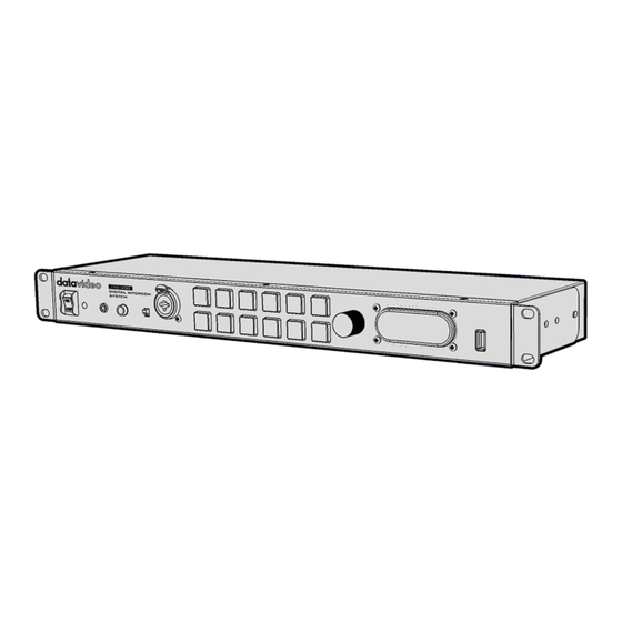
This chapter contains introductory guides to operations on the front panel and connections at the rear. Base Unit On/Off Switch Powers the ITC-300 On / Off. Red LED indicates that unit is switched on. XLR Microphone Socket Composite XLR / ¼” (6.3mm) Microphone Input Jack for either a Condenser or Dynamic Gooseneck Microphone. - Page 11 The buttons will also indicate if any channel is paging, the paging channel will flash in green until the page is answered. These channel buttons can also be used to gain access to certain built-in features on the ITC-300. See the section on Function Keys for details.
-
Page 12: Rear Panel
For powering the connected USB gooseneck light (supplied). Rear Panel The ITC-300 is a standalone model supporting 8 channel communication. It also powers the beltpack directly. Beltpack Channel Ports Each of the 8 channels has an Ethernet connector that carries bi-directional signals between the ITC-300 and the ITC-300SL. - Page 13 For FW Upgrade. Tally Inputs A / B Tally Inputs A & B provide direct connection to the Datavideo switcher. They supply bi-color tally information to the ITC-300SL; RED indicates Live and GREEN indicates Cued. Tally Input A carries bicolor tally information of Channels 1 ~ 4 and Tally Input B carries bicolor tally information of Channels 5 ~ 8.
-
Page 14: Belt Pack
Belt Pack As shown in the diagram below, before use, connect the beltpack’s communication port located at the opposite end of the control panel to the base unit’s beltpack channel ports with an Ethernet cable. The subsequent chapter provides introductory guides to operations using the beltpack’s control panel. - Page 15 3.5mm MIC / Headset. Call Button Sends a paging message to the ITC-300 Base Unit. The base unit’s channel button will flash green and there will be an audible tone each time the button is pressed.
-
Page 16: Device Pairing Procedure
The Pairing function is designed to configure channel assignment of the ITC-300 intercom system to the connected beltpacks. You will only be allowed to assign one powered ON beltpack to one channel of the ITC-300 intercom system at a time. Power of the rest of the beltpacks should be turned OFF. -
Page 17: Check The Beltpack's Paired Channel With The Base Unit
On the front panel of the base unit, press SHIFT and HOLD buttons then hold for more than 3 seconds to enter the ITC-300 Intercom System in PP mode. Once in the PP mode successfully, you will see the following button LED behaviors. -
Page 18: Noise Reduction
Once cleared, the channel button LED will flash green three times, indicating that the settings have been cleared. Note: No action needs to be taken on the beltpack. Noise Reduction If you hear excessive background noise, enabling the noise reduction feature lowers the noise level. -
Page 19: Function Keys
CHANNEL buttons should turn white from red. All Communication Once the ITC-300’s All Communication mode is enabled, the base unit will then be able to establish communication with all beltpacks immediately. First press the base unit’s ALL button, which turns red from green... -
Page 20: Cross Communication (Party Mode)
When the operator of the base unit talks, all paired beltpacks will be able to hear him at the same time. However, carrier of each individual beltpack will not be able to hear communications of other channels. For example, beltpack 1 will not be able to hear the communication between beltpack 4 and the base unit. -
Page 21: Audio In
Audio IN The ITC-300’s AUDIO IN mode allows input of external analog audio to the intercom system. To enable the AUDIO IN mode, press and hold the base unit’s SHIFT button then press Channel 6 button which should turn red from green, indicating that the AUDIO IN mode is enabled. -
Page 22: Factory Reset
Press and hold the SHIFT and ALL buttons for more than 3 seconds and all buttons on the ITC-300 base unit’s front panel should be illuminated in the order of red, green and white colors. The base unit’s parameters will have returned to the factory defaults... -
Page 23: Tally Input
Tally Input If you are using the ITC-300 with a Datavideo product, you do not need to worry about tally information, as it has already been customized for the ITC-300. However, if you are using the ITC-300 with equipment of other manufacturers, please see the following tables for PIN definitions of the ITC-300’s Tally A and B inputs. -
Page 24: Firmware Update
Firmware Update Datavideo usually releases new firmware containing new features or reported bug fixes from time to time. Customers can either download the firmware as they wish or contact their local dealer or reseller for assistance. This section outlines the firmware upgrade process which should take approximately few minutes to complete. -
Page 25: Upgrade Procedure
Upgrade Procedure Run FlashUpdate_SL_Vxx to update the ITC-300SL firmware and FlashUpdate_MB_Vxx to update the ITC-300 firmware. Turn the ITC-300 base unit off and on the PC, select “Device is connected via Ethernet.”... - Page 26 If you are upgrading the ITC-300SL, press the CALL button before turning on the ITC-300. If you are upgrading the ITC-300, press the SHIFT button before turning on the ITC-300. Select “Automatically update the device to latest firmware version” then click...
- Page 27 Click Yes to start the firmware upgrade. If you see the screen below, it means the firmware upgrade is in progress. After the firmware is successfully upgraded, click Finish and shut down the ITC- 300 base unit.
-
Page 29: Dimensions
Dimensions ITC-300 All measurements in millimeters (mm) -
Page 30: Specifications
Specifications Base Station (ITC-300) Front Power On/Off Switch 3.5mm Stereo Jack Socket x 1 (For Headphone / Microphone combination) Headset Impedance 8~600 ohms 100mW (min) Input Microphone Level -67dB Pin definition Tip: Mic / Ring: Phone / Sleeve: GND MIC / Headset ¼”... - Page 31 Act as the power source for connected light USB Light Socket +5 V output current up to 500mA. 3W Speaker is disabled when headphones or mic / headset Built-in Speaker are plugged into the ITC-300 Rear RJ45 Port RJ45 x 8 (ITC-300) Tally In...
- Page 32 Power Switch / VR with Multifunction Switch (Power ON/OFF the beltpack, Volume Control adjusts the headphone volume) Tally LED Bi-Color LED – RED indicates LIVE / GREEN Indicates CUED Power LED Red light Link LED Yellow light Red light – Outgoing call Call LED Green light –...
-
Page 33: Service & Support
Jun-04.2018 Ver: E2...
Need help?
Do you have a question about the ITC-300 and is the answer not in the manual?
Questions and answers