Sign In
Upload
Download
Table of Contents
Contents
Add to my manuals
Delete from my manuals
Share
URL of this page:
HTML Link:
Bookmark this page
Add
Manual will be automatically added to "My Manuals"
Print this page
×
Bookmark added
×
Added to my manuals
Manuals
Brands
Datavideo Manuals
Intercom System
ITC300HP2K
Instruction manual
Datavideo ITC300HP2K Instruction Manual
Digital intercom system
Hide thumbs
1
Table Of Contents
2
3
4
5
6
7
8
9
10
11
12
13
14
15
16
17
18
19
20
21
22
23
24
25
26
27
28
29
30
31
32
33
34
35
36
37
38
39
40
page
of
40
Go
/
40
Contents
Table of Contents
Bookmarks
Table of Contents
Table of Contents
Fcc Compliance Statement
Warnings and Precautions
Warranty
Standard Warranty
Three Year Warranty
Disposal
Product Overview
Features
System Diagram
System Overview
Base Unit
Rear Panel
Belt Pack
RJ-1M Protective Shield
Control Panel
Device Pairing Procedure
Check the Belt Pack's Paired Channel with the Base Unit
Clearing Channel Assignment
Noise Reduction
Function Keys
Check the Belt Pack's Channel Assignment
Group Communication
All Communication
Cross Communication (Party Mode)
Belt Packs
Simultaneously under Party Mode
Audio in
Panel's Backlight Brightness
Mute Mode
Factory Reset
Tally Input
Tallya Input Pin Definition
Tallyb Input Pin Definition
Tally Cables for Connecting Datavideo Switchers and Itc-300
Firmware Update
Firmware Upgrade Requirements
System Connections
Upgrade Procedure
Frequently-Asked Questions
Dimensions
Specifications
Service & Support
Advertisement
Quick Links
Download this manual
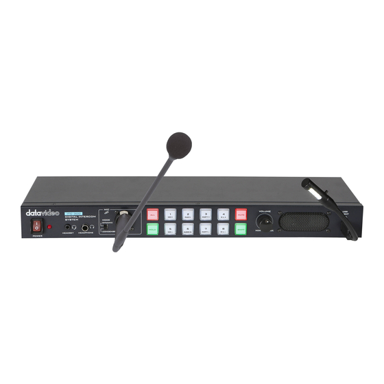
DIGITAL
INTERCOM SYSTEM
ITC-300
Table of
Contents
Previous
Page
Next
Page
1
2
3
4
5
Advertisement
Table of Contents
Need help?
Do you have a question about the ITC300HP2K and is the answer not in the manual?
Ask a question
Questions and answers
Related Manuals for Datavideo ITC300HP2K
Intercom System Datavideo ITC-300 Instruction Manual
Digital intercom system (33 pages)
Recording Equipment Datavideo TLM-170V Instruction Manual
Hd 12-channel ob van studio (17 pages)
Intercom System Datavideo ITC-100 User Manual
8 channel intercom / talkback system (16 pages)
Intercom System Datavideo ITC-100 KF1000 Instruction Manual
8 channel intercom / talkback system for se-1000 (14 pages)
Intercom System Datavideo ITC-100 Instruction Manual
Intercom system (24 pages)
Intercom System Datavideo ITC-100SL Instruction Manual
Intercom belt pack (8 pages)
Intercom System Datavideo ITC-100SL Instruction Manual
Intercom belt pack (11 pages)
Intercom System Datavideo ITC-200E Quick Start Manual
Intercom expansion unit (11 pages)
Intercom System Datavideo ITC-200E Instruction Manual
Intercom expansion unit (9 pages)
Intercom System Datavideo ITC-300SL Instruction Manual
Digital intercom system (40 pages)
Intercom System Datavideo RP-31 Instruction Manual
Itc-100 patch panel (6 pages)
This manual is also suitable for:
Itc-300
Itc300hp1k
Itc-300sl
Table of Contents
Print
Rename the bookmark
Delete bookmark?
Delete from my manuals?
Login
Sign In
OR
Sign in with Facebook
Sign in with Google
Upload manual
Upload from disk
Upload from URL


Need help?
Do you have a question about the ITC300HP2K and is the answer not in the manual?
Questions and answers