Table of Contents
Advertisement
Quick Links
R2TE - R4TE
R2TED - R4TED
R2CE - R2CED
I
Manuale di uso e manutenzione
Use and maintenance manual
GB
F
Manuel d'utilisation et d'entretien
D
Bedienungs - und Wartungsanleitung
pag. 1
E
Manual de uso y manutenciòn
,, 31
NL
Handleiding voor gebruik en onderhound
,, 61
Bycnherwbb
Bycnherwbb
Bycnherwbb
Bycnherwbb
Bycnherwbb
RUS
a e y r w b j y b h j d f y b /
a e y r w b j y b h j d f y b /
a e y r w b j y b h j d f y b /
a e y r w b j y b h j d f y b /
a e y r w b j y b h j d f y b /
,, 91
pag. 121
,, 151
,, 201
gj
gj
ecnfyjdrt
ecnfyjdrt
b
b
gj
gj
gj
ecnfyjdrt
ecnfyjdrt
ecnfyjdrt
b
b
b
Advertisement
Table of Contents

Related Manuals for Pentair Pool Products Nocchi R4TE


Summary of Contents for Pentair Pool Products Nocchi R4TE
- Page 1 R2TE - R4TE R2TED - R4TED R2CE - R2CED Manuale di uso e manutenzione pag. 1 pag. 121 Manual de uso y manutenciòn ,, 151 ,, 31 Use and maintenance manual Handleiding voor gebruik en onderhound ,, 61 ,, 201 Bycnherwbb Bycnherwbb ecnfyjdrt...
- Page 2 DICHIARAZIONE CE DI CONFORMITÀ EC DECLARATION OF CONFORMITY La Ditta PENTAIR WATER ITALY Srl dichiara sotto la propria The Company PENTAIR WATER ITALY Srl declares, under its own responsibility, that the below mentioned electropumps are responsabilità che le elettropompe sotto indicate sono conformi ai compliant with the relevant Health and Safety standards, specified Requisiti Essenziali di Sicurezza e di Tutela della Salute di cui alle Direttive 98/37, 2006/95/CE, 2004/108/CE e loro successive...
-
Page 3: Table Of Contents
CHAPTER 1 - INTRODUCTION ....................... 3 PARTICULAR SIGNS ..........................3 GENERAL INFORMATION........................3 PRELIMINARY CHECKS........................3 CAPITOLO 2 - TECHNICAL FEATURES ..................4 FIELD LIMITATIONS ...........................4 INBOUND SIGNAL FEATURES ......................4 CHAPTER 3 - INSTALLATION ......................5 COOLING THE MOTOR ........................5 MOTOR PUMP ELECTRICAL CONNECTION..................5 ELECTRICAL CONNECTION BOARD –... - Page 4 HISTORY (SAVED)..........................24 SIGNAL TABLE..........................24 ALARM TABLE ..........................25 ERROR TABLE..........................25 CHAPTER 7 - RESETTING AND FACTORY SETTINGS .............. 28 GENERAL SYSTEM RESET ......................28 TO RESET FACTORY SETTINGS....................28 SOFTWARE VERSION........................28 8 – DATA PLATE ........................... 29 CAPITOLO 9 – GUARANTEE......................30 Page 2 of 3 2 - GB -...
-
Page 5: Chapter 1 - Introduction
CHAPTER 1 - INTRODUCTION PARTICULAR SIGNS The attention sign indicates the procedures requiring your absolute attention, otherwise you may cause damage to the machine or equipment connected to it. The danger sign indicates the procedures requiring your absolute attention, otherwise you may get an electric shock. The note sign offers important information highlighted outside the text to which it refers. -
Page 6: Capitolo 2 - Technical Features
Check the machine is not damaged. If you receive an incorrect or damaged machine, notify PENTAIR WATER ITALY or the authorised dealer within and not after 10 (ten) days from date of purchase. CHAPTER 2 - TECHNICAL FEATURES For the motor pump refer to the information contained in the specific manuals. Do not use the product in environments with acid, corrosive and/or inflammable gas. -
Page 7: Chapter 3 - Installation
CHAPTER 3 - INSTALLATION The installation operations must be performed by expert, qualified personnel. Use specific guards and equipment as per safety standards. Fully comply with safety and accident prevention standards in force. Carefully read the use and maintenance manual for the pump. Stop the pump with the external command connected to the INI contacts (paragraphs 3.5 and 3.6) when the circuit is completely closed or create a bypass circuit. -
Page 8: Electrical Connection Board - Power Board
Before switching on or after a long period without power, the display may flash; this indicates the internal clock must be regulated (see chap. 5.3.1). ELECTRICAL CONNECTION BOARD – POWER BOARD LINE - LINE Æ Power entry - J3 Æ Alarm exit Æ... -
Page 9: Connections Board For A Single Pump - Control Board
CONNECTIONS BOARD FOR A SINGLE PUMP - CONTROL BOARD x RS-485 Æ Communication port x INI Æ INIBIT input: NC external contact or NO for START/STOP command x S.P. Æ External Set Point (EST) command: NA contact x NTC Æ NTC sensor input to control temperature or potentiometer (see diagram) x TRASD. -
Page 10: Capitolo 4 - Functioning
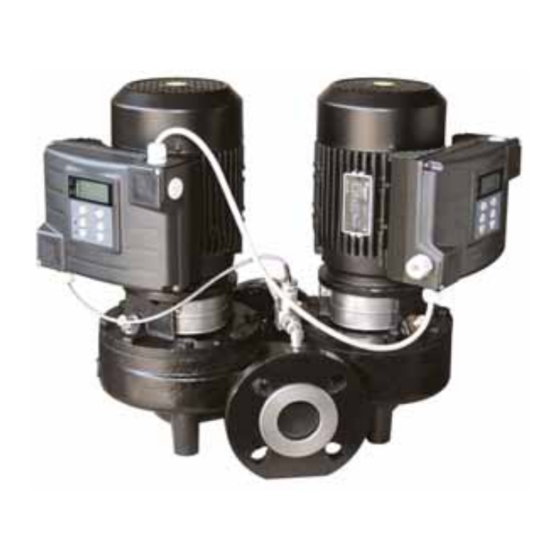
CHAPTER 4 - FUNCTIONING PRODUCT DESCRIPTION The system is comprised of an "in-line" electrical pump or circulator, a CPS electronic control system (inverter) and a pressure system to check differential pressure provided by the pump. The pumps are typically employed as circulation pumps for heating and/or air conditioning systems (R2TE- R4TE) or for heating (R2CE) only with variable loads. -
Page 11: Changes To Settings
The dP-c setting maintains the system's differential pressure constant at the Hset value entered based on load changes. Proportional differential pressure dP-v setting. The dP-v setting varies the delivery value of the head from the Hset value entered to half its Hset/2 value based on load changes. -
Page 12: To Select A Setting Mode
4.2.3 TO SELECT A SETTING MODE Type of system. System features Type of setting recommended Relatively low system resistance Two-tube systems with to heating/air conditioning. thermostatic and/or area valves. • head less than 2 m. • Natural circulation. • With low load losses in parts of the system where the total quantity of water flows (boiler, heat exchanger, distribution lines... -
Page 13: Guide To Performance Settings
4.2.4 GUIDE TO PERFORMANCE SETTINGS dP-c dP-v Work point on the maximum Move left from the work point. Read the H1 delivery value and set the performance curve. pump to this work point Work point within the adjustment Move left from the work point. From the adjustment curve go field. -
Page 14: Capitolo 5 - Programming
CHAPTER 5 - PROGRAMMING CONTROL PANEL DESCRIPTION The control panel is shown in fig. 1 fig.1 Press the START/STOP button to start and/or stop the pump. DESCRIPTION OF SIGNALS ON DISPLAY When running normally (that is, in the absence of any alarms) press the MODE button to alternate the various displays available: 1. -
Page 15: Programming Menu
Day of the week. 3. A Æ Absorbed current Current absorbed by the pump in Ampere. Frequency graph indicator Day of the week Æ Time 4. hh:mm Time. Day of the week. Frequency graph indicator 5. Complementary pump status (unit only) “STB”... -
Page 16: Programming Clock/Day
5.3.1 PROGRAMMING CLOCK/DAY During the first installation phase, the module display flashes to indicate the internal clock needs updating. The clock is equipped with a battery to maintain the time and date for 24 hours if there is no power. DESCR PARAMETER MENU... - Page 17 press MODE to go from the scroll between menus on the display. 1. TO CHOSE THE TYPE OF CONTROL Choose the type of control required between constant differential pressure "dPc", proportional pressure RdPv" or constant frequency "Frq". 2. TO SET THE SET POINT SET POINT 1: head or frequency required by the system.
- Page 18 5. ANALOGUE SETTING In A The default function is deactivated (In A=5). To activate this function set In A <>5 and install the potentiometer (as described in Chapter 3.5) or the command with 0-5V. In this case, the set point for the head of the pump will be reduced or increased based on the external signal.
- Page 19 fig.2 Page 17 of 18 17 - GB -...
-
Page 20: Advanced Parameters
5.3.3 ADVANCED PARAMETERS Key sequence to access the advanced menu button pressed for 10 seconds DESCR PARAMETER MENU DESCRIPTION DEFAULT DISPLAY NAME Unit of TPR E Pressure unit of measurement measurement Number of SET SET N Number of set points used POINTS Motor rotation Motor rotation direction... - Page 21 fig.3 Page 19 of 20 19 - GB -...
-
Page 22: Installation Parameters
5.3.4 INSTALLATION PARAMETERS Key sequence to access the installation menu Last button pressed for 10 seconds During the modification of the parameters, the symbol on the display lights up. Use the MODE key to change various parameters. With the buttons it is possible to modify the values. - Page 23 Minimum Parameter defining minimum motor rotation frequency. frequency INF F Maximum Parameter defining maximum motor rotation frequency. frequency SUP F Reactivity factor Parameter defining the speed with which the motor responds to changes in pressure. The lower the setting the faster the motor's response.
- Page 24 1st start-up Waiting time between the first lack of water reading and first attempt to automatically restart the system (minutes). The module will not attempt to restart if this parameter is set to zero. 1440 RIP 1 2nd restart Waiting time between the first restart and the second attempt to automatically restart the system (minutes).
-
Page 25: Manual Start Of Motor/Priming
MANUAL START OF MOTOR/PRIMING This procedure is applicable when you want to manually start the system or prime the pump. It is possible to manually start the motor by pressing the following sequence of buttons: Buttons sequence with pump off The pump remains on until the last button is pressed Last button pressed for 10 seconds During manual start-up, the motor rotates at maximum speed and the pressure... -
Page 26: Signals, Alarm Status And Errors
SIGNALS, ALARM STATUS AND ERRORS HISTORY (SAVED) Key sequence Press ESC for 5 seconds Push ESC button Key sequence Press MODE to scroll the error log Push MODE button Key sequence Press STOP to see the hour and the date of the event Push STOP button (when the clock has been set correctly) SIGNAL TABLE... -
Page 27: Alarm Table
ALARM TABLE MESS DESCRIPTION ACTION DISPLAY Error temporary Check the water level in the first absence of water. This occurs No water alarm - tank or the aqueduct pressure. when water is absent and the temporary Wait programmed restart mechanism been attempted restart or press the activated. - Page 28 error control board cannot the LINE Led switches off and communication with the power part. after which turn power back on. This alarm condition closes the J3 If the error condition occurs again, contact on the power board for contact your nearest assistance possible external signals (alarm centre.
- Page 29 This alarm condition closes the J3 which restart the system. contact on the power board for If the error occurs again, contact possible external signals (alarm your nearest assistance centre. light, siren, etc.) Undefined error This error occurs when Wait for a few minutes. If the unforeseen error takes place.
-
Page 30: Chapter 7 - Resetting And Factory Settings
CHAPTER 7 - RESETTING AND FACTORY SETTINGS 7.1 GENERAL SYSTEM RESET Press only as a last resort to restart the system Triggers a general module reset and reloads set values saved in eeprom. Press as a last resort only in order to restart the module. -
Page 31: Data Plate
8 – DATA PLATE Type of motor pump Current Phase number IP grade Voltage Software version Frequency Registration (manufacturing date) Absorbed current Page 29 of 30 29 - GB -... -
Page 32: Capitolo 9 - Guarantee
CHAPTER 9 – GUARANTEE This device is covered by legal guarantee based on the current standards in force for the country of purchase, relating to manufacturing malfunctions and defects and/or those of the material used. The guarantee is limited to repairs or replacements, in the assistance centres authorised by PENTAIR WATER ITALY Srl, for the pump or parts deemed malfunctioning or faulty.
Need help?
Do you have a question about the Nocchi R4TE and is the answer not in the manual?
Questions and answers