
Subscribe to Our Youtube Channel
Related Manuals for Federal Signal Corporation WV450XL Series


Summary of Contents for Federal Signal Corporation WV450XL Series
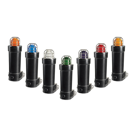
- Page 1 Model WV450XL Series GRP LED Beacon for Use in Hazardous and Marine Locations *magenta and yellow not shown Installation and Maintenance Instructions 25500104A Rev. A0 1113 Printed in U.S.A.
- Page 2 Warranty – Seller warrants all goods for five years on parts and 2-1/2 years on labor, under the following conditions and exceptions: Seller warrants that all goods of Seller's manufacture will conform to any descriptions thereof for specifications which are expressly made a part of this sales contract and at the time of sale by Seller such goods shall be commercially free from defects in material or workmanship.
-
Page 3: Table Of Contents
Contents Safety Messages to Installers and Users ..........5 Overview of Model WV450XL Series ............ 6 Certification ..................... 7 Unpacking the Beacon ................8 Mounting the Beacon ................8 Safety Messages for Wiring ..............9 Wiring the WV450XLD Flameproof Models ........10 Wiring the 24 Vdc Model WV450XLD ..........11... - Page 4 Figure 6 Connections Ex de DC or AC beacons........15 Figure 7 Location of DIP switch for flash patterns ........ 18 Tables Table 1 SW1 settings for flash patterns ..........18 Table 2 Replacement parts ..............23 © 2013 Federal Signal Corporation. All rights reserved. Model WV450XL Series...
-
Page 5: Safety Messages To Installers And Users
After installation, test the beacon system to ensure that it is operating properly. • After testing is complete, provide a copy of this instruction sheet to all personnel. • Establish a procedure to routinely check the beacon system for proper activation and operation. Model WV450XL Series... -
Page 6: Overview Of Model Wv450Xl Series
The housing is made of corrosion resistant components, which dramatically reduces the cost of long-term maintenance. The WV450XL Series beacons use all of the latest techniques in non-metallic housing construction. The body of the product is glass reinforced polyester (GRP) and 316 stainless steel hardware. -
Page 7: Certification
úmido. 2) O valor de capacitância de peças metálicas desenterradas é 10 pF, quando medido por IEC / EN 60079-0. 3) Contate o fabricante para obter informação sobre a dimensão das juntas à prova de fogo. Model WV450XL Series... -
Page 8: Unpacking The Beacon
Ex d VERSION M20 GLAND ENTRY 2 POSITIONS 136.5 [5.37] 63.5 [2.50] 114.3 [4.50] 289.7 [11.41] 113.3 [4.46] 57.2 [2.25] 41.3 [1.63] 12.7 [0.50] 41.3 [1.63] GUARD 82.6 [3.25] LENS COVER ASSY ø39.4 [ø1.55] X 2 GRUB SCREW Model WV450XL Series... -
Page 9: Safety Messages For Wiring
EExde COVER SCREWS CERTIFICATION LABEL WARNING LABEL See Figures 1 and 2. The Federal Signal WV450XL Series LED 290A7613 beacon is mounted using a mounting bracket fixed to the base of the unit. Install the enclosure on the selected support surface using the three 9.0 mm (0.35 in) mounting holes. -
Page 10: Wiring The Wv450Xld Flameproof Models
Cable termination for these models should be in accordance with specifications applying to the application. It is recommended that all cables and cores should be fully identified. Use the appropriate cable gland for the application. Gland entry threads are M20-1.5 x 6H. Model WV450XL Series... -
Page 11: Wiring The 24 Vdc Model Wv450Xld
See Figure 3. Connect the positive (+) power source wire to the terminal block screw marked “ + .” Connect the negative (–) power source wire to the terminal block screw marked “–.” Figure 3 Connections for 24 Vdc model Model WV450XL Series... -
Page 12: Wiring The 110-220 Vac Model Wv450Xld
See Figure 4 . Connect the line (hot) power source wire to the terminal block screw marked “ .” Connect the neutral (common) power source wire to the terminal block screw marked “ .” Connect the ground wire to the terminal block clamp marked GND. Model WV450XL Series... -
Page 13: Wiring The Wv450Xle Increased Safety Models
• WV450XLE 24 Vdc • WV450XLE 110-220 Vac The maximum wire gauge is 2.5 mm (12 AWG). The wire must be rated 85 °C or higher. Use only stranded or multiple strand cable to terminate the beacon. Model WV450XL Series... -
Page 14: Figure 5 Terminal Block For Model 450Xle
To disengage the clamp, insert the tip of the screwdriver into the small openings near the top. Insert the stripped wire into the larger opening and remove the screwdriver to engage the wire clamp. Figure 5 Terminal block for Model 450XLE Model WV450XL Series... -
Page 15: Wiring The 24 Vdc Model Wv450Xle
Ensure that the gasket is properly seated to maintain the IP rating. Do not overtighten the cover screws. Figure 6 Connections Ex de DC or AC beacons TO LINE BUSHING SUPPLY IN = L1, N1, G1 LOOP OUT = L2, N2, G2 290A7619 Model WV450XL Series... -
Page 16: Wiring The 110-220 Vac Model Wv450Xle
Do not open the device in the presence of explosive gases in the atmosphere. BURN HAZARD—The LED emitter gets hot enough to burn you. Always allow the emitter to cool before handling it. Model WV450XL Series... - Page 17 Installation and Maintenance Instructions The Model WV450XL Series beacon has eight flash patterns that are selected by setting a DIP switch on the PCB. See Figure 7 and Table 1. Tool needed: • 2.0 mm A/F hexagon key • 2 mm blade-tip screwdriver To select a pattern: Disconnect power to the beacon.
-
Page 18: Figure 7 Location Of Dip Switch For Flash Patterns
Table 1 SW1 settings for flash patterns 1 2 3 Description Steady On Blink (60 FPM) Random Blink Rotate (120 RPM) Variable Pulse Strobe Simulation (60 FPM) Strobe Simulation (90 FPM) Severe Alert Model WV450XL Series... -
Page 19: Safety Messages To Maintenance Personnel
• Any competent site personnel can carry out the replacement of the LED array. Other repairs should be undertaken by returning the unit to Federal Signal Corporation or by an authorized repairer of Ex equipment. • If you acquired a significant quantity of units, then it is recommended that spares are also made available. -
Page 20: Maintaining The Beacon
Cleaning the Enclosure The fixture should be cleaned periodically to maintain maximum light output. Use only mild, non-abrasive cleaning agents. The glass dome should be regularly inspected for scratches and chips, and if damaged must be replaced. Model WV450XL Series... -
Page 21: Replacing The Led Array
Use the hexagon key to unscrew the grub screw on the dome cover assembly one full turn. Remove the cover from the housing by turning the cover counter-clockwise. If the dome cover assembly will not unscrew, back out the grub screw a few additional turns. Model WV450XL Series... - Page 22 To ensure O-ring compression, there should be a maximum gap of 0.3 mm (0.012 in) between the faces of the enclosure and cover. Turn the grub screw one full turn or until the screw contacts the housing. d. Reconnect power to the beacon. Model WV450XL Series...
-
Page 23: Ordering Accessories And Replacement Parts
LED Array, Amber Beacon K14700030-A LED Array, Blue Beacon K14700030-B LED Array, White Beacon K14700030-W LED Array, Green Beacon K14700030-G LED Array, Magenta Beacon K14700030-W LED Array, Red Beacon K14700030-R LED Array, Yellow Beacon K14700030-W Dome Guard K8595107 Model WV450XL Series... - Page 24 Installation and Maintenance Instructions Model WV450XL Series...
Need help?
Do you have a question about the WV450XL Series and is the answer not in the manual?
Questions and answers