Table of Contents
Advertisement
Advertisement
Table of Contents

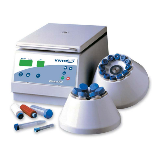
Summary of Contents for VWR Clinical 200
-
Page 2: Table Of Contents
CONTENTS 1 PRODUCT DESCRIPTION 1.1 Usage in accordance with safety standards 1.1.1 General Information 1.1.1.1 Hazards and precautions 1.1.1.2 Brief description 1.1.1.3 Safety standards 1.1.1.4 Included items 1.1.1.5 Warranty 1.2 Installation 1.2.1 Installation of the centrifuge 1.2.1.1 Unpacking the centrifuge 1.2.1.2 Space requirements 1.2.1.3 Installation 1.3 Technical Data... -
Page 3: Product Description
1 PRODUCT DESCRIPTION Usage in accordance with safety standards 1.1.1 General information 1.1.1.1 Hazards and precautions Before operating the centrifuge, please read this instruction manual carefully! This centrifuge must not be operated by unqualified personnel not familiar with the correct use of the unit. •... -
Page 4: Brief Description
1 PRODUCT DESCRIPTION The manufacturer is responsible for safety and reliability of the centrifuge, only if: • the unit is operated in accordance with this instruction manual. • modifications, repairs or other adjustments are performed by factory-authorized personnel and the electrical installation of the related location corresponds to the IEC- regulations. -
Page 5: Included Items
1 PRODUCT DESCRIPTION 1.1.1.4 Included items Following parts are supplied as accessories with each centrifuge: • 2 fine-wire fuses 1,25 AT (230 V) • 1 fine-wire fuse 0,50 AT (230 V) • 2 fine-wire fuses 2,50 AT (120 V) • 1 fine-wire fuse 0,10 AT (120 V) •... -
Page 6: Installation
Test obligations To be filled in by purchaser: Inventory-No.: ____________________________________ Check-No.: ____________________________________ Location: ____________________________________ Maintenance contract: ____________________________________ Your service department VWR International Phone 800-932-5000 or 610-431-1700 www.vwr.com Your agent ___________________________________ Manufacturer reserves the right to alter product specifications without notice. -
Page 7: Operation
2 OPERATION 2.1 Installation of rotors 2.1.1 Mounting and loading angle rotors Clean the motor shaft as well as the rotor mounting boring with a clean, grease-free piece of cloth. Place the rotor onto the motor shaft, ensuring that the cross pin aligns correctly with the rotor slot (see photos 1 and 2). -
Page 8: Mounting And Loading Swing Out Rotors
2 OPERATION 2.1.2 Mounting and loading swing out rotors Clean the motor shaft, as well as the shaft hole in the rotor with a clean and grease- free cloth. Place the rotor on the motor shaft, taking care that the cross pin is sitting in the rotor slot (photo 1 and photo 2). -
Page 11: Nomogram - To Convert The Speed Into Rcf-Value
2 OPERATION 2.2.5 Nomogram – to convert Speed into RCF-value CHART to determine the relative centrifugal force (RCF-value). This value is the multiplier to the gravitational pull of earth (g). Speed (x g) (rpm) Radius (mm) Example: Measure the distance in mm from the center of the rotor (radius) to the most outer part (bottom of the tube) in the used bucket, tube rack or rotor . -
Page 14: Maintenance
3 MAINTENANCE 3.1 Service and maintenance 3.1.1 Maintenance and cleaning Maintenance: Maintenance of the centrifuge is confined to keeping the rotor , the rotor chamber and the rotor accessories clean as well as to regularly lubricating the rotor insert bolts of a swing out rotor (if available). -
Page 16: Trouble Shooting
4 TROUBLE SHOOTING 4.2.2 Description of the error message system Error messages are shown in the “SPEED” display (see photo 17). There are two different kinds of errors. • Errors No. 1 – 49 (forced stop) If one of these errors occur, the rotor decelerates from preset speed down to 0. As soon as the rotor stops, the error message can be reset by opening and closing the lid of the centrifuge. - Page 17 4 TROUBLE SHOOTING Error No. 2: Permanent imbalance signal • Cause: Incorrect positioning of imbalance sensor • Solution: Imbalance sensor needs to be readjusted (call service department) • Cause: Imbalance sensor is defective • Solution: Imbalance sensor needs to be replaced (call service department) Error No.
- Page 18 • Cause: Control switch of lid lock is defective • Solution: Call service department VWR International, Inc. Goshen Corporate Park West 1310 Goshen Parkway PO Box 2656 West Chester, PA 19380-0906 Technical modification rights reserved.


Need help?
Do you have a question about the Clinical 200 and is the answer not in the manual?
Questions and answers