Table of Contents
Advertisement
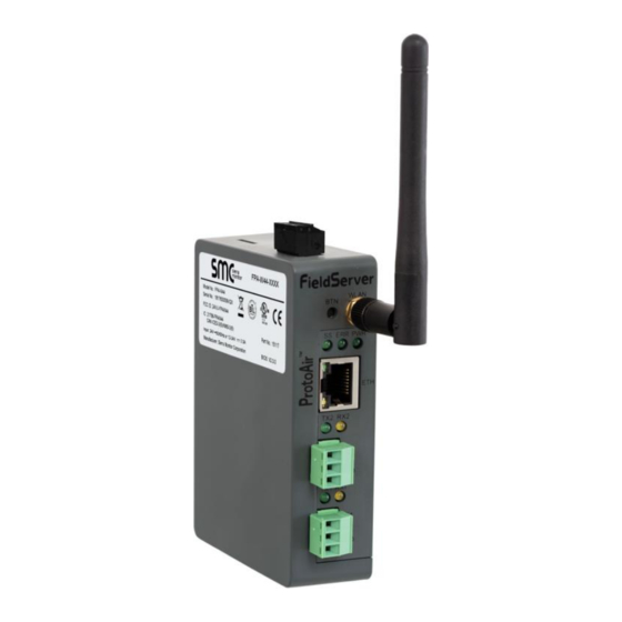
ProtoAir FPA-W44
Start-up Guide
For Interfacing Siemens Products:
FC410, MAG6000, MASS6000, FST030
To Building Automation Systems and SMC Cloud:
BACnet MS/TP, BACnet/IP, Modbus TCP/IP and EtherNet/IP
APPLICABILITY & EFFECTIVITY
Explains ProtoAir hardware and how to install it.
The instructions are effective for the above as of January 2019.
Document Revision: 1.A
Web Configurator
Template Revision: 3
Advertisement
Table of Contents

Related Manuals for Siemens ProtoAir FPA-W44


Summary of Contents for Siemens ProtoAir FPA-W44
- Page 1 ProtoAir FPA-W44 Start-up Guide For Interfacing Siemens Products: FC410, MAG6000, MASS6000, FST030 To Building Automation Systems and SMC Cloud: BACnet MS/TP, BACnet/IP, Modbus TCP/IP and EtherNet/IP APPLICABILITY & EFFECTIVITY Explains ProtoAir hardware and how to install it. The instructions are effective for the above as of January 2019.
-
Page 2: Technical Support
Thank you for purchasing the ProtoAir for Siemens. Please call Siemens for technical support of the ProtoAir product. Sierra Monitor Corporation does not provide direct support. If Siemens needs to escalate the concern, they will contact Sierra Monitor Corporation for assistance. -
Page 3: Quick Start Guide
Siemens ProtoAir Start-up Guide Quick Start Guide 1. Record the information about the unit. (Section 3.1) 2. Set COM settings for the device that will be connected to ProtoAir. (Section 3.3) 3. Connect the ProtoAir 3 pin RS-485 R1 port to the RS-485 network connected to each of the devices. -
Page 4: Table Of Contents
Siemens ProtoAir Start-up Guide TABLE OF CONTENTS Certification ............................7 BTL Mark – BACnet ® Testing Laboratory ..................7 Introduction ............................8 ProtoAir Gateway ..........................8 ProtoAir Setup ............................9 Record Identification Data ......................9 Point Count Capacity and Registers per Device ................9 Configuring Modbus Device Communications ................ - Page 5 Siemens ProtoAir Start-up Guide Appendix C Vendor Information – Siemens ................... 44 Appendix C.1 FC410 Modbus RTU Mappings to BACnet and EtherNet/IP ..........44 Appendix C.2 MAG6000 Modbus RTU Mappings to BACnet and EtherNet/IP ........45 Appendix C.3 MASS6000 Modbus RTU Mappings to BACnet and EtherNet/IP ........47 Appendix C.4 FST030 Modbus RTU Mappings to BACnet and EtherNet/IP ..........
- Page 6 Figure 30: FS-GUI Passwords Page ......................40 Figure 31: Password Recovery Page ......................40 Figure 32: FS-GUI Wi-Fi AP Network Settings ................... 41 Figure 33: DIN Rail ............................42 Figure 34: ProtoAir FPA-W44 Dimensions ....................43 Figure 35: Specifications ..........................65 Page 6 of 66...
-
Page 7: Certification
Siemens ProtoAir Start-up Guide CERTIFICATION BTL Mark – BACnet ® 1 Testing Laboratory The BTL Mark on ProtoAir is a symbol that indicates that a product has passed a series of rigorous tests conducted by an independent laboratory which verifies that the product correctly implements the BACnet features claimed in the listing. -
Page 8: Introduction
ProtoAir Gateway The ProtoAir wireless gateway is an external, high performance building automation multi-protocol gateway that is preconfigured to automatically communicate between Siemens’ devices (hereafter simply called “device”) connected to the ProtoAir and automatically configures them for BACnet/IP, BACnet MS/TP, EtherNet/IP and Modbus TCP/IP. -
Page 9: Protoair Setup
Siemens ProtoAir Start-up Guide PROTOAIR SETUP Record Identification Data Each ProtoAir has a unique part number located on the side or the back of the unit. This number should be recorded, as it may be required for technical support. The numbers are as follows:... -
Page 10: Configuring Modbus Device Communications
Siemens ProtoAir Start-up Guide Configuring Modbus Device Communications 3.3.1 Input COM Settings on Any Device Connected to the ProtoAir • Any connected serial device MUST have the same baud rate, data bits, stop bits, and parity settings as the ProtoAir. -
Page 11: Interfacing Protoair To Devices
Siemens ProtoAir Start-up Guide INTERFACING PROTOAIR TO DEVICES Device Connections to ProtoAir The ProtoAir has a 3-pin Phoenix connector for connecting RS-485 devices on the R1 port. NOTE: Use standard grounding principles for RS-485 GND. ProtoAir Device Pins Pin #... -
Page 12: Wiring Field Port To Rs-485 Serial Network
Siemens ProtoAir Start-up Guide Wiring Field Port to RS-485 Serial Network • Connect the RS-485 network wires to the 3-pin RS-485 connector on the R2 port. (Figure Use standard grounding principles for RS-485 GND • See Section for information on connecting to an Ethernet network. -
Page 13: Bias Resistors
Siemens ProtoAir Start-up Guide Bias Resistors R1 Bias Resistor DIP Switches (2 and 3) R2 Bias Resistor DIP Switches (2 and 3) Figure 8: Bias Resistor DIP Switches To enable Bias Resistors, move both the BIAS- and BIAS+ dip switches to the right as shown in... -
Page 14: Termination Resistor
Siemens ProtoAir Start-up Guide Termination Resistor R1 Termination Resistor DIP Switch (1) R2 Termination Resistor DIP Switch (1) Figure 9: Termination Resistor DIP Switch If the ProtoAir is the last device on the serial trunk, then the End-Of-Line Termination Switch needs to be enabled. -
Page 15: Power-Up Protoair
Siemens ProtoAir Start-up Guide Power-Up ProtoAir Check power requirements in the table below: Power Requirement for ProtoAir External Gateway Current Draw Type ProtoAir Family 12VDC 24V DC/AC FPA-W44 (Typical) 250mA 125mA NOTE: These values are ‘nominal’ and a safety margin should be added to the power supply of the host system. -
Page 16: Connect The Pc To The Protoair
Siemens ProtoAir Start-up Guide CONNECT THE PC TO THE PROTOAIR There are two ways to connect the PC to the ProtoAir, either by Ethernet cable (Section 5.1) or Wi-Fi Access Point (Section 5.2). Connecting to the ProtoAir via Ethernet First, connect a Cat-5 Ethernet cable (straight through or cross-over) between the local PC and ProtoAir. -
Page 17: 5.1.1.2 Changing The Ip Address Of The Protoair With Fieldserver Toolbox
Siemens ProtoAir Start-up Guide 5.1.1.2 Changing the IP Address of the ProtoAir with FieldServer Toolbox • Ensure that FieldServer Toolbox is loaded onto the local PC. Otherwise, download the FieldServer-Toolbox.zip via the Sierra Monitor website’s Software Downloads. • Extract the executable file and complete the installation. -
Page 18: Connecting To The Protoair Over Wi-Fi Access Point
Siemens ProtoAir Start-up Guide Connecting to the ProtoAir Over Wi-Fi Access Point When the ProtoAir is first powered up, the Wi-Fi Access Point will be enabled allowing direct connection to the ProtoAir with Wi-Fi. To connect to the ProtoAir Wi-Fi Access Point: •... -
Page 19: Configure The Protoair
Siemens ProtoAir Start-up Guide CONFIGURE THE PROTOAIR Accessing the ProtoAir Web Configurator • Navigate to the IP Address of the ProtoAir on the local PC using one of two methods: Open a web browser and enter the IP Address of the ProtoAir; the default Ethernet address is 192.168.1.24, the default Wi-Fi Access Point address is 192.168.50.1... -
Page 20: Setting Protoair Active Profiles
Siemens ProtoAir Start-up Guide Setting ProtoAir Active Profiles • In the Web Configurator, the Active Profiles are shown below the configuration parameters. The Active Profiles section lists the currently active device profiles, including previous Web Configurator additions. This list is empty for new installations, or after clearing all configurations. -
Page 21: 6.3.1 Verify Device Communications
Siemens ProtoAir Start-up Guide • To add an active profile to support a device, click the Add button under the Active Profiles heading. This will present a drop-down menu underneath the Current profile column that lists all the available profiles. -
Page 22: Bacnet: Setting Node_Offset To Assign Specific Device Instances
Siemens ProtoAir Start-up Guide BACNET: SETTING NODE_OFFSET TO ASSIGN SPECIFIC DEVICE INSTANCES • Follow the steps outlined in Section to access the ProtoAir Web Configurator. • The Node_Offset field shows the current value (default = 50,000). The values allowed for a BACnet Device Instance can range from 1 to 4,194,303 •... -
Page 23: How To Start The Installation Over: Clearing Profiles
Siemens ProtoAir Start-up Guide HOW TO START THE INSTALLATION OVER: CLEARING PROFILES • Follow the steps outlined in Section to access the ProtoAir Web Configurator. • At the bottom-left of the page, click the “Clear Profiles and Restart” button. •... -
Page 24: Network Settings
Siemens ProtoAir Start-up Guide NETWORK SETTINGS Navigate to the FS-GUI Network Settings • Open the FS-GUI page. From the Web Configurator page, click on the blue “Diagnostics & Debugging” button in the bottom right corner of the screen Figure 18: Web Configurator Page – Diagnostics Button •... -
Page 25: Figure 20: Generic Fs-Gui Navigation Panel - Network Settings
Siemens ProtoAir Start-up Guide • Click the orange arrow next to the ProtoAir CN number and title to expand the tree. • Click on the orange arrow next to Setup to expand the tree. • Click on Network Settings. Figure 20: Generic FS-GUI Navigation Panel –... -
Page 26: Change The Protoair Ip Address
Siemens ProtoAir Start-up Guide Change the ProtoAir IP Address Configure the IP settings of the ProtoAir in the following methods: • When using the Ethernet port to connect to the local network (Section 9.2.1). • When connecting the ProtoAir to a local wireless access point, configure the Wi-Fi Client Settings in the ProtoAir (Section 9.2.2). -
Page 27: 9.2.1 Update Wired Network Settings
Siemens ProtoAir Start-up Guide 9.2.1 Update Wired Network Settings IP Settings tab is the landing page when selecting Network Settings on the navigation tree. To change the IP settings, follow these instructions: • Enable DHCP Client State to automatically assign IP Settings or modify the settings manually as needed, via these fields: IP Address, Netmask, Default Gateway and Domain Name Server1/2. -
Page 28: 9.2.2 Update Wi-Fi Client Settings
Siemens ProtoAir Start-up Guide 9.2.2 Update Wi-Fi Client Settings From the FS-GUI Network Settings landing page, click on the Wi-Fi Client tab. To change the Wi-Fi client settings, follow these instructions: • Set the Wi-Fi Status to ENABLED for the ProtoAir to communicate with other devices via Wi-Fi. -
Page 29: 9.2.3 Common Settings
Siemens ProtoAir Start-up Guide 9.2.3 Common Settings From the FS-GUI Network Settings landing page, click on the Common tab. NOTE: Default is Primary Connection is Ethernet. To change the primary connection when both Ethernet and Wi-Fi Client connections are available: •... -
Page 30: Appendix A Troubleshooting
Siemens ProtoAir Start-up Guide Appendix A Troubleshooting Appendix A.1 Lost or Incorrect IP Address • Ensure that FieldServer Toolbox is loaded onto the local PC. Otherwise, download the FieldServer-Toolbox.zip via the Sierra Monitor website’s Software Downloads. • Extract the executable file and complete the installation. -
Page 31: Appendix A.2 Viewing Diagnostic Information
Siemens ProtoAir Start-up Guide Appendix A.2 Viewing Diagnostic Information • Type the IP Address of the ProtoAir into the web browser or use the FieldServer Toolbox to connect to the ProtoAir. • Click on Diagnostics Button, then click on view, and then on connections. -
Page 32: Appendix A.3 Checking Wiring And Settings
Siemens ProtoAir Start-up Guide Appendix A.3 Checking Wiring and Settings • No COMS on Modbus RTU side. If the Tx/Rx LEDs are not flashing rapidly then there is a COM issue. To fix this, check the following: A.4) Visual observations of LEDs on ProtoAir... -
Page 33: Appendix A.4 Led Diagnostics For Communications Between Protoair And Devices
Siemens ProtoAir Start-up Guide Appendix A.4 LED Diagnostics for Communications Between ProtoAir and Devices See the diagram below for ProtoAir LED Locations. Diagnostic LEDs Description The SS LED will light if the unit is not getting a response from one or more of the configured devices. -
Page 34: Appendix A.5 Taking A Fieldserver Diagnostic Capture
Siemens ProtoAir Start-up Guide Appendix A.5 Taking a FieldServer Diagnostic Capture When there is a problem on-site that cannot easily be resolved, perform a diagnostic capture before contacting support so that support can quickly solve the problem. There are two methods for taking diagnostic captures: •... - Page 35 Siemens ProtoAir Start-up Guide • Step 1: Take a Log Click on the diagnose icon of the desired device Ensure “Full Diagnostic” is selected (this is the default) NOTE: If desired, the default capture period can be changed. Page 35 of 66...
- Page 36 Siemens ProtoAir Start-up Guide Click on “Start Diagnostic” Wait for Capture period to finish, then the Diagnostic Test Complete window will appear • Step 2: Send Log Once the Diagnostic test is complete, a .zip file is saved on the PC Choose “Open”...
-
Page 37: Appendix A.5.2 Using Fs-Gui
Siemens ProtoAir Start-up Guide Appendix A.5.2 Using FS-GUI Diagnostic Capture via FS-GUI is only available on FieldServers with a bios updated/released on November 2017 or later. Completing a Diagnostic Capture through the FieldServer allows network connections (such as Ethernet and Wi-Fi) to be captured. -
Page 38: Appendix A.6 Wi-Fi Signal Strength
Siemens ProtoAir Start-up Guide Appendix A.6 Wi-Fi Signal Strength Wi-Fi <60dBm – Excellent <70dBm – Very good <80dBm – Good >80dBm – Weak Figure 28: Wi-Fi Signal Strength Listing NOTE: If the signal is weak or spotty, try to improve the signal strength by checking the antenna and the ProtoAir position. -
Page 39: Appendix B Additional Information
Siemens ProtoAir Start-up Guide Appendix B Additional Information Appendix B.1 Updating Firmware To load a new version of the firmware, follow these instructions: 1. Extract and save the new file onto the local PC. 2. Open a web browser and type the IP Address of the FieldServer in the address bar. -
Page 40: Appendix B.3 Securing Protoair With Passwords
Siemens ProtoAir Start-up Guide Appendix B.3 Securing ProtoAir with Passwords Access to the ProtoAir can be restricted by enabling a password on the FS-GUI Passwords page – click Setup and then Passwords in the navigation panel. There are 2 access levels defined by 2 account names: Admin and User. -
Page 41: Appendix B.4 Wi-Fi Access Point Network Settings
Siemens ProtoAir Start-up Guide Appendix B.4 Wi-Fi Access Point Network Settings From the FS-GUI Network Settings landing page, click on the Wi-Fi AP tab. To change the Wi-Fi AP settings, follow these instructions: • The Access Point Status Field must be ENABLED to allow connecting to the ProtoAir via Wi-Fi. -
Page 42: Appendix B.5 Mounting
Siemens ProtoAir Start-up Guide Appendix B.5 Mounting The ProtoAir can be mounted using the DIN rail mounting bracket on the back of the unit. Din Rail Bracket Figure 33: DIN Rail Page 42 of 66... -
Page 43: Appendix B.6 Physical Dimension Drawing
Siemens ProtoAir Start-up Guide Appendix B.6 Physical Dimension Drawing Power Port Wi-Fi Antenna Socket R2 Serial Port R1 Serial Port Figure 34: ProtoAir FPA-W44 Dimensions Page 43 of 66... -
Page 44: Appendix C Vendor Information - Siemens
NOTE: All Modbus TCP/IP registers are the same as the Modbus RTU registers for the serial device. If this point list is needed, contact Siemens technical support. The Modbus TCP/IP node address of the device is also the same as the Modbus RTU node address. -
Page 45: Appendix C.2 Mag6000 Modbus Rtu Mappings To Bacnet And Ethernet/Ip
Siemens ProtoAir Start-up Guide Calibration Factor Density Calibration Offset Density Calibration Factor Dens. Comp. Tube Temp. Dens. Comp. Frame Temp. Massflow Simulation Value Density Simulation Value Tube Temperature Simulation Value Frame Temperature Simulation Value Volumeflow Simulation Value Enable Simulation Alarm Group 1... - Page 46 Siemens ProtoAir Start-up Guide Limit Relay Setpoint min. Limit Relay Setpoint max. Limit Relay Hysteresis Error number Batch Quantity BatchQuantity_XXX BatchQuantityWR_XXX Batch Compensation Batch Time error on/off Batch time Batch overrun on/off Batch overrun error Batch counter up/down Batch Time constants...
-
Page 47: Appendix C.3 Mass6000 Modbus Rtu Mappings To Bacnet And Ethernet/Ip
Siemens ProtoAir Start-up Guide Error log list Reg 19 Error log list Reg 20 Error log list Reg 21 Error log list Reg 22 Error log list Reg 23 Error log list Reg 24 Error log list Reg 25 Error log list Reg 26... - Page 48 Siemens ProtoAir Start-up Guide MODBUS module HW version DA_U16_XXX[15] Last Coil Error DA_U16_XXX[16] Last Coil Error DA_U16_XXX[17] Last HoldReg Error DA_U16_XXX[18] Last HoldReg Error DA_U16_XXX[19] Flow direction DA_U16_XXX[20] Massflow max. DA_Flt_XXX[9] Volumeflow max. DA_Flt_XXX[10] Density min. DA_Flt_XXX[11] Density max. DA_Flt_XXX[12] Sensor temperature min.
- Page 49 Siemens ProtoAir Start-up Guide Calibration factor DA_Flt_XXX[38] Correction factor DA_Flt_XXX[39] Sensor TC DA_Flt_XXX[40] Density parm. A DA_Flt_XXX[41] Density parm. B DA_Flt_XXX[42] Density TC DA_Flt_XXX[43] Density offset DA_Flt_XXX[44] Density factor DA_Flt_XXX[45] Table slope DA_Flt_XXX[46] Fraction offset DA_Flt_XXX[47] Operating time DA_U32_XXX[2] USM II Error pending list Reg 01...
-
Page 50: Appendix C.4 Fst030 Modbus Rtu Mappings To Bacnet And Ethernet/Ip
Siemens ProtoAir Start-up Guide Display line 1 DA_U16_XXX[109] Display line 2 DA_U16_XXX[110] Display line 3 DA_U16_XXX[111] Massflow unit DA_U16_XXX[112] Massflow point DA_U16_XXX[113] Volumeflow unit DA_U16_XXX[114] Volumeflow point DA_U16_XXX[115] Fraction A + B unit DA_U16_XXX[116] Fraction A point DA_U16_XXX[117] Fraction B point... - Page 51 Siemens ProtoAir Start-up Guide Status output CH4 DA_U16_XXX[4] Input current CH4 DA_Flt_XXX[30] Digital input signal CH4 DA_U16_XXX[5] Input current CH5 DA_Flt_XXX[31] Input current CH6 DA_Flt_XXX[32] Totalizer 1 value DA_Flt_XXX[33] Totalizer 1 set DA_U16_XXX[6] Totalizer 1 direction DA_U16_XXX[7] Totalizer 1 preset value...
- Page 52 Siemens ProtoAir Start-up Guide Calibration reference temperature DA_Flt_XXX[53] Pipe thermal expansion DA_Flt_XXX[54] Calibration reference pressure DA_Flt_XXX[55] Pipe modulus elasticity DA_Flt_XXX[56] Upstream pipe geometry DA_U16_XXX[51] Upstream distance DA_U16_XXX[52] Downstream pipe geometry DA_U16_XXX[53] Downstream distance DA_U16_XXX[54] Expected sound velocity DA_Flt_XXX[57] Fixed medium temperature...
- Page 53 Siemens ProtoAir Start-up Guide Zero adjust progress DA_U16_XXX[76] Last zero adjust status DA_U16_XXX[77] Protect calibration table DA_U16_XXX[78] Enable multipoint calibration DA_U16_XXX[79] Asymmetric calibration table DA_U16_XXX[80] Calibration point DA_Flt_XXX[98] Calibration value DA_Flt_XXX[99] Calibration table command DA_U16_XXX[81] Multipoint calibration status DA_U16_XXX[82] Calibration point 1...
- Page 54 Siemens ProtoAir Start-up Guide Flow Velocity Low flow cut-off DA_Flt_XXX[161] Flow Velocity Upper alarm limit DA_Flt_XXX[162] Flow Velocity Upper warning limit DA_Flt_XXX[163] Flow Velocity Lower warning limit DA_Flt_XXX[164] Flow Velocity Lower alarm limit DA_Flt_XXX[165] Flow Velocity Hysteresis DA_Flt_XXX[166] Sound Velocity Upper alarm limit...
- Page 55 Siemens ProtoAir Start-up Guide Totalizer 1 Volume upper alarm limit DA_Flt_XXX[229] Totalizer 1 Volume upper warning limit DA_Flt_XXX[230] Totalizer 1 Volume lower warning limit DA_Flt_XXX[231] Totalizer 1 Volume lower alarm limit DA_Flt_XXX[232] Totalizer 1 Volume alarm hysteresis DA_Flt_XXX[233] Totalizer 1 Mass upper alarm limit...
- Page 56 Siemens ProtoAir Start-up Guide Ch 2 Upper range value dimensionless DA_Flt_XXX[288] Ch 2 Lower range value dimensionless DA_Flt_XXX[289] Ch 2 Upper range value current DA_Flt_XXX[290] Ch 2 Lower range value current DA_Flt_XXX[291] Ch 2 Upper range value viscosity DA_Flt_XXX[292] Ch 2 Lower range value viscosity...
- Page 57 Siemens ProtoAir Start-up Guide General Ch 3 Operation mode DA_U16_XXX[110] General Ch 3 Active/passive operation DA_U16_XXX[111] Ch 3 Process value DA_U16_XXX[112] Ch 3 Flow direction DA_U16_XXX[113] Ch 3 Current mode DA_U16_XXX[114] Ch 3 Upper range value volume flow DA_Flt_XXX[336] Ch 3 Lower range value volume flow...
- Page 58 Siemens ProtoAir Start-up Guide Ch 3 Pulse Output Flow direction DA_U16_XXX[126] Ch 3 Pulse Output Amount of volume DA_Flt_XXX[390] Ch 3 Pulse Output Amount of mass DA_Flt_XXX[391] Ch 3 Pulse Output Amount of standard volume DA_Flt_XXX[392] Ch 3 Pulse Output Pulses per amount...
- Page 59 Siemens ProtoAir Start-up Guide Ch 4 Current Output Upper range value current DA_Flt_XXX[429] Ch 4 Current Output Lower range value current DA_Flt_XXX[430] Ch 4 Current Output Upper range value viscosity DA_Flt_XXX[431] Ch 4 Current Output Lower range value viscosity DA_Flt_XXX[432]...
- Page 60 Siemens ProtoAir Start-up Guide Ch 4 Status Output Polarity DA_U16_XXX[167] Ch 4 Status Output On delay DA_Flt_XXX[473] Ch 4 Status Output Off delay DA_Flt_XXX[474] Ch 4 Status Output Forced value DA_U16_XXX[168] Ch 4 Discrete Input Input leading edge function DA_U16_XXX[169]...
- Page 61 Siemens ProtoAir Start-up Guide View 1 View DA_U16_XXX[193] View 1 1st value DA_U16_XXX[194] View 1 2nd value DA_U16_XXX[195] View 1 3rd value DA_U16_XXX[196] View 1 4th value DA_U16_XXX[197] View 1 5th value DA_U16_XXX[198] View 1 6th value DA_U16_XXX[199] View 1 Trend scale mode...
- Page 62 Siemens ProtoAir Start-up Guide View 6 Trend scale upper limit DA_Flt_XXX[526] Active alarm items 1 DA_U32_XXX[26] Active alarm items 2 DA_U32_XXX[27] Active alarm items 4 DA_U32_XXX[28] Active alarm items 5 DA_U32_XXX[29] Active alarm items 6 DA_U32_XXX[30] Active alarm items 7...
- Page 63 Siemens ProtoAir Start-up Guide Ch 4 Current input value DA_Flt_XXX[546] Ch 4 Error status DA_U16_XXX[271] Ch 4 Digital input value DA_U16_XXX[272] Proc Value 1 Process value DA_U16_XXX[273] Proc Value 1 Maximum value DA_Flt_XXX[547] Proc Value 1 Minimum value DA_Flt_XXX[548] Proc Value 1 Reset logging...
- Page 64 Siemens ProtoAir Start-up Guide CH 2 Output Current Base density DA_Flt_XXX[579] CH 2 Output Current Liquident DA_Flt_XXX[580] CH 2 Output Current API gravity DA_Flt_XXX[581] CH 2 Output Current Base API gravity DA_Flt_XXX[582] CH 2 Output Current Specific gravity DA_Flt_XXX[583] CH 2 Output Current Base specific gravity...
-
Page 65: Appendix D Reference
Siemens ProtoAir Start-up Guide Appendix D Reference Appendix D.1 Specifications ProtoAir FPA-W44 One 3-pin Phoenix connector with: RS-485/RS-232 port (TX+/RX-/gnd) One 3-pin Phoenix connector with: RS-485 (Tx+/Rx-/gnd) Electrical Connections One 3-pin Phoenix connector with: Power port (+/-/Frame-gnd) One Ethernet 10/100 BaseT port... -
Page 66: Appendix E Limited 2 Year Warranty
Siemens ProtoAir Start-up Guide Appendix E Limited 2 Year Warranty Sierra Monitor Corporation warrants its products to be free from defects in workmanship or material under normal use and service for two years after date of shipment. Sierra Monitor Corporation will repair or replace any equipment found to be defective during the warranty period.
Need help?
Do you have a question about the ProtoAir FPA-W44 and is the answer not in the manual?
Questions and answers