Siemens SIMATIC IOT Quick Install Manual
Hide thumbs
Also See for SIMATIC IOT:
- Quick install manual (2 pages) ,
- Operating instructions manual (64 pages) ,
- Operating instructions manual (133 pages)
Advertisement
Quick Links
1
Mounting the device
Gerät einbauen
Before mounting and commissioning – Vor Einbau und Inbetriebnahme
1.1
IMPORTANT: observe all documents enclosed with the device and the operating instructions manual
before mounting and connecting the device. You find the complete documentation of the internet
http://www.siemens.com/simatic-ipc-doku-portal
WICHTIG: Beachten Sie alle dem Gerät beiliegenden Dokumente und die Betriebsanleitung, bevor
Sie das Gerät einbauen und anschließen. Die vollständige Dokumentation des Geräts finden Sie im
Internet
http://www.siemens.de/simatic-ipc-doku-portal
The manual symbol refers to detailed information in the operating instructions.
Das Handbuchsymbol weist auf detaillierte Informationen in der Betriebsanleitung hin.
Scope of delivery – Lieferumfang
1.2
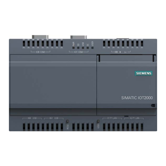
One SIMATIC IOT device, one terminal connector, one mounting accessory kit including one mounting
clamp, two mounting brackets and screws. No accessories such as Micro SD card and cables.
Ein SIMATIC IOT-Gerät, ein Klemmenanschluss, ein Montagezubehör-Set mit einer Montage-
-klemme, zwei Montagewinkeln und -schrauben; kein Zubehör wie Micro SD-Karte und -Kabel.
1.3
Valid Mounting positions – Zulässige Einbaulagen
Vertical/vertikal, preferred/Empfohlen
Horizontal/horizontal
When the device is used in the area of Industrial Control Equipment in accordance with
UL61010‑2‑201, note that the device is classified as "Open Equipment ". A UL61010‑2‑201 conform
enclosure is therefore a mandatory requirement for approval or operation according to
UL61010‑2‑201.
Beachten Sie beim Einsatz im Bereich Industrial Control Equipment entsprechend UL61010‑2‑201,
dass das Gerät als "Open Equipment" klassifiziert ist. Voraussetzung für die Zulassung bzw.
den Betrieb nach UL61010‑2‑201 ist deshalb der Einbau des Geräts in ein der UL61010‑2‑201
entsprechendes Gehäuse.
Free space required around the device - Erforderlicher Freiraum um das Gerät
50 mm
50 mm
1.4 Mounting the device – Gerät anbauen
Vertical mounting on DIN rails / vertikale Hutschienenmontage
1
Torque: 0.6 Nm
2
3
1.4
Mounting the device – Gerät anbauen
Horizontal mounting on DIN rails / horizontale Hutschienenmontage
Vertical wall mounting / vertikale Wandmontage
Torque: 0.6 Nm
Horizontal wall mounting / horizontale Wandmontage
Torque: 0.6 Nm
2
Connecting the device
Gerät anschließen
2.1
Connecting the function earth – Anschließen der Funktionserde
1
50 mm
2.2
Connecting the power supply – Stromversorgung anschließen
The device must only be connected to a 12 to 24 VDC power supply which meets the requirements
50 mm
of safe extra low voltage (SELV) according to IEC/EN/DIN EN/UL 61010-1.
If there are voltage peaks on power supply lines, use a protective device in the form of a varistor
(MOV) UMOV = U-rated x 1.2 (BLITZDUCTOR BVT AVD 24 (918 422) or compatible).
Das Gerät darf nur an eine DC 12...24-V‑Stromversorgung angeschlossen werden, die den Anforde-
rungen einer sicheren Kleinspannung (SELV) gemäß der IEC/EN/DIN EN/UL 61010‑1 entspricht.
Gibt es Spannungsspitzen auf den Stromversorgungsleitungen, dann verwenden Sie eine
Schutzeinrichtung in Form eines Varistors
(MOV) UMOV = Urated x 1.2 (BLITZDUCTOR BVT AVD 24 (918 422) oder kompatibel).
50 °C
1
POWER
OFF
0 °C
D C 1 2
P o w e
S u p p ly
4
Click!
Torque: 0.6 Nm
1
2
1 1
2 2
3 3
3
REST
REST
1
2
M4
²
2.5 mm
3
Torque: 1 Nm
2
4
5
t o 2 4
V
r
3
Tightening torque: 0.56 Nm
Wire range: 0.75 to 2.5 mm
Rated temperature of wire: 70
Conductor material: Cu
6
2.3
Switching on the device –
40 °C
1
0 °C
POWER
ON
4
Click!
D C 1 2
t o 2 4
V
P o w e
r
S u p p ly
45 °C
3
Expand device
0 °C
Gerät erweitern
3.1 Install Arduino shield – Arduino-Shield einbauen
1
REST
REST
40 °C
0 °C
Customize the shield cover according to the arduino shield.
Die Schutzabdeckung entsprechend dem Arduino Shield anpassen.
3.2 Remove the top housing
2
T20
3
Loosen the top housing. Carefully press with the blade of a flat-blade screwdriver in the marked
2
recesses and carefully pull on the appropriate place on the top housing of the enclosure.
Lösen Sie das obere Gehäuse. Drücken Sie die Klinge eines Schlitzschraubendrehers vorsichtig
in die gekennzeichneten Aussparungen und ziehen Sie vorsichtig an einer geeigneten Stelle des
oberen Gehäuses.
3
Remove the top housing with shield cover.
Nehmen Sie das obere Gehäuse mit Schutzabdeckung ab.
3
2
0.5 x 2
2
°C
Gerät einschalten
2
PWR
1
2
3
Remove the power plug and marked
1
screws.
Ziehen Sie den Netzstecker ab und
entfernen Sie die gekennzeichneten
Schrauben.
2
Advertisement

Related Manuals for Siemens SIMATIC IOT


Summary of Contents for Siemens SIMATIC IOT
- Page 1 Vertical wall mounting / vertikale Wandmontage 45 °C Torque: 0.6 Nm One SIMATIC IOT device, one terminal connector, one mounting accessory kit including one mounting clamp, two mounting brackets and screws. No accessories such as Micro SD card and cables. Expand device...
- Page 2 Insert the Mini PCIe card in the Mini PCIe interface and fix it with two M2 screws. Operating system and software for the SIMATIC IOT devices are freely programmable and are For half size Mini PCIe card, you need to move one standoff from A to B. Then install the half downloaded from the Micro SD card when the device is booted.
Need help?
Do you have a question about the SIMATIC IOT and is the answer not in the manual?
Questions and answers