Nibe PCS 44 Installer Manual
Passive cooling for nibe f1145, f1245
Hide thumbs
Also See for PCS 44:
- Installer manual (76 pages) ,
- Installer manual (40 pages) ,
- Installer manual (36 pages)
Table of Contents

Related Manuals for Nibe PCS 44


Summary of Contents for Nibe PCS 44
- Page 1 PCS 44 Installatörshansbok Passiv kyla för NIBE F1145, F1245 Installer manual Passive cooling for NIBE F1145, F1245 Installateurhandbuch Passive Kühlung für NIBE F1145, F1245 IHB 0935-1 031433...
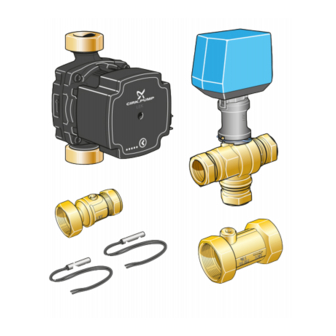
- Page 3 Svenska, Installatörshandbok - PCS 44 Allmänt 1 st Shuntventil med ställdon Detta tillbehör används då NIBE F1145/F1245 installeras 2 st Temperaturgivare i en anläggning med frikyla. 1 st Isoleringstejp Innehåll 4 st Buntband 1 st Pump 2 st Utbytespackning 1 st...
- Page 4 Köldbärarkretsen skall förses med tryckexpansionskärl. Eventuellt befintligt nivåkärl byts ut. Backventil, shuntventil och cirkulationspump Montera den bipackade backventilen mellan de två T-rörsanslutningarna till PCS 44 närmast värmepum- pen på köldbärare in (se principschema). Montera shuntventilen (QN18) på framledningen till Temperaturgivarna monteras med buntband tillsammans fläktkonvektorn (port 1) så...
- Page 5 Avstängningsventil QM42 Kylsystem QM12 Påfyllningsventil Tillbehörskort Nivåkärl QN18 Växelventil, kyla Säkerhetsventil GP13 Cirkulationspump, kyla Backventil EP13 Fläktkonvektor EP12 Kollektor Principschema F1145 med PCS 44 -BT1 -QM12 -CM2 -EQ1-AA5 -QM42 -XL15 -FL3 -EP13 -BT65 -QM34 -EB100 -BT64 -GP13 -QN18 -RM5 -EP12...
- Page 6 Elektrisk installation och ledningsdragning skall AA3-X4 utföras enligt gällande bestämmelser. AA3-X4 F1145/F1245 ska vara spänningslös vid installa- tion av PCS 44. Elscheman finns i slutet av denna monteringsanvisning. AA3-X4 Anslutning av matning Anslut spänningsmatningen till plint X1 enligt bild. F1145...
- Page 7 Anslutning av givare TÄNK PÅ! Reläutgångarna på tillbehörskortet får max be- Använd kabeltyp LiYY, EKKX eller likvärdig. lastas med 2 A (230 V) totalt. Framledningsgivare, kyla (BT64) Anslut framledningsgivaren till AA5-X2:21-22. Anslutning av cirkulationspump (GP13) Anslut cirkulationspumpen (GP13) till AA5-X9:2 (230 V), Returledningsgivare, kyla (BT65) AA5-X9:1 (N) och X1:3 (PE).
- Page 8 (max 2 A) på ingångskortet (AA3), plint X7. Ansluts kyllägesindikering till plint X7 måste det väljas i meny 5.4. Programinställningar Programinställningen av PCS 44 kan göras via startguiden eller direkt i menysystemet. Startguiden Startguiden visas vid första uppstart efter värmepumpsin- stallationen, men finns även i meny 5.7.
-
Page 9: Table Of Contents
English, Installer manual - PCS 44 General Shunt valve with actuator This accessory is used when NIBE F1145/F1245 is installed Temperature sensor in an installation with passive cooling. Insulation tape Contents Cable ties Pump Replacement gasket Pump insulation Heating pipe paste... - Page 10 Check valve, mixing valve and circulation pump Install the supplied check valve between two T-pipe connections to PCS 44 nearest the heat pump on Install the temperature sensors with cable ties with the brine in (see the outline diagram). heat conducting paste and aluminium tape. Then insulate with supplied insulation tape.
- Page 11 Filler valve Accessory card Level vessel QN18 Reversing valve, cooling Safety valve GP13 Circulation pump, cooling Non-return valve EP13 Fan convectors EP12 Collector Outline diagram F1145 with PCS 44 -BT1 -QM12 -CM2 -EQ1-AA5 -QM42 -XL15 -FL3 -EP13 -BT65 -QM34 -EB100 -BT64...
- Page 12 F1145/F1245 out in accordance with the stipulations in force. AA3-X4 AA3-X4 F1145/F1245 must not be powered when in- stalling PCS 44. The electrical circuit diagram is at the end of these install- ation instructions. AA3-X4 Connecting the supply Connect the power supply to terminal block X1 as illus- trated.
- Page 13 Connecting sensors Caution The relay outputs on the accessory card can have Use cable type LiYY, EKKX or similar. a max load of 2 A (230 V) in total. Flow temperature sensor, cooling (BT64) Connect the flow temperature sensor to AA5-X2:21-22. Connection of the circulation pump (GP13) Connect the circulation pump (GP13) to AA5-X9:2 (230 Return line sensor, cooling (BT65)
-
Page 14: Program Settings
If cooling mode indication is connected to terminal block X7 it must be selected in menu 5.4, see Program settings Program setting of PCS 44 can be performed via the start guide or directly in the menu system. Start guide The start guide appears upon first start-up after heat pump installation, but is also found in menu 5.7. -
Page 15: Aa5-S2
Deutsch, Installateurhandbuch - PCS 44 Allgemeines 1 St. Mischventil mit Stellvorrichtung Dieses Zubehör wird benötigt, wenn NIBE F1145/F1245 2 St. Fühler in einer Anlage mit passiver Kühlung installiert wird. 1 St. Isolierband Inhalt 4 St. Kabelbinder 1 St. Pumpe 2 St. - Page 16 Die Fühler werden mit Kabelbinder, Wärmeleitpaste und pumpe Aluminiumband angebracht. Anschließend sind sie mit Montieren Sie das beiliegende Rückschlagventil zwi- dem beiliegenden Isolierband zu umwickeln. schen den beiden T-Rohranschlüssen für PCS 44 an der Wärmepumpe am Wärmequelleneingang (siehe HINWEIS! Prinzipskizze). Fühler- und Kommunikationskabel dürfen nicht Montieren Sie das Mischventil (QN18) am Vorlauf zum in der Nähe von Starkstromleitungen verlegt...
- Page 17 Absperrventil QM42 Kühlsystem QM12 Einfüllventil Zusatzplatine Niveaugefäß QN18 Umschaltventil, Kühlung Sicherheitsventil GP13 Umwälzpumpe, Kühlung Rückschlagventil EP13 Kälteverbraucher EP12 Kollektor Prinzipskizze F1145 mit PCS 44 -BT1 -QM12 -CM2 -EQ1-AA5 -QM42 -XL15 -FL3 -EP13 -BT65 -QM34 -EB100 -BT64 -GP13 -QN18 -RM5 -EP12...
- Page 18 Anschluss der Kommunikationsleitung Elektrischer Anschluss Die erste Zusatzplatine ist direkt mit der Wärmepumpen- klemme AA3-X4 zu verbinden. Bei mehreren Zusatzplati- HINWEIS! nen muss die folgende Platine mit der vorherigen in Reihe Alle elektrischen Anschlüsse müssen von einem geschaltet werden. geprüften Elektriker ausgeführt werden. Verwenden Sie Kabeltyp LiYY, EKKX oder gleichwertig.
- Page 19 Fühleranschluss ACHTUNG! Die Relaisausgänge an der Zusatzplatine dürfen Verwenden Sie Kabeltyp LiYY, EKKX oder gleichwertig. insgesamt mit maximal 2 A (230 V) belastet Vorlauffühler, Kühlung (BT64) werden. Verbinden Sie den Vorlauffühler mit AA5-X2:21-22. Anschluss der Umwälzpumpe (GP13) Rücklauffühler, Kühlung (BT65) Verbinden Sie die Umwälzpumpe (GP13) mit AA5-X9:2 Verbinden Sie den Rücklauffühler mit AA5-X2:19-20.
- Page 20 Wenn die Kühlmodusanzeige mit Klemme X7 verbunden wird, muss dies in Menü 5.4 ausgewählt werden. Programmeinstellungen Die Programmeinstellung von PCS 44 kann per Startassis- tent oder direkt im Menüsystem vorgenommen werden. Startassistent Der Startassistent erscheint bei der ersten Inbetriebnahme nach der Wärmepumpeninstallation.
- Page 21 Elschema/Wiring diagram/Elektrischer schaltplan...
- Page 24 NIBE AB Sweden Järnvägsgatan 40 Box 14 SE-285 21 Markaryd Phone +46 433 73 000 Telefax +46 433 73 190 info@nibe.se www.nibe.se...
Need help?
Do you have a question about the PCS 44 and is the answer not in the manual?
Questions and answers