Nibe FLM Installer Manual
Exhaust air module
Hide thumbs
Also See for FLM:
- Installer manual (36 pages) ,
- User manual (24 pages) ,
- Installer manual (32 pages)
Table of Contents
Advertisement
Quick Links
Advertisement
Table of Contents

Related Manuals for Nibe FLM


Summary of Contents for Nibe FLM
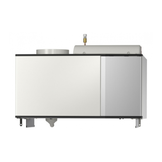
- Page 1 IHB EN 1850-5 INSTALLER MANUAL 331702 Exhaust air module NIBE FLM...
-
Page 3: Table Of Contents
Brine side Contact information Condensation water hose General ventilation connection Ventilation flow Adjusting ventilation Dimension and ventilation connections Installation alternative 5 Electrical connections General Connections 6 Commissioning and adjusting Preparations Filling and venting Start-up and inspection NIBE FLM Table of Contents... -
Page 4: Important Information
MARKING The CE mark is obligatory for most products sold in the EU, regardless of where they are made. IP21 Classification of enclosure of electro-technical equip- ment. Chapter 1 | Important information NIBE FLM... - Page 5 System vented Antifreeze Expansion vessel Particle filter Safety valve Shut off valves Circulation pump setting Checking the condensation water seal Trim valve Electricity (page Connections Phase voltage Supply connected 230 V Circuit fuses NIBE FLM Chapter 1 | Important information...
-
Page 6: Delivery And Handling
10 mm is left to reduce the risk of noise and Assembly of any vibrations being propagated. NIBE FLM is installed on top of the ground heat pump or freestanding on brackets. Noise from the circulation pump or fan can be transferred to the brackets. -
Page 7: Supplied Components
Undo the screws at the upper edge LOCATION Lift the side hatches upwards and twist the cover The bag of supplied items is placed on top of NIBE FLM. outwards slightly. Assembly takes place in the reverse order. NIBE FLM... -
Page 8: The Design Of The Exhaust Air Module
3 The design of the exhaust air module BT21 XL32 QM21 XL31 BT20 PF 1 HQ10 AA100 AA5-S2 BT20 XL31 QM21 XL32 BT26 BT27 HQ10 AA100 BT21 EP16 XL40 BT27 BT26 Chapter 3 | The design of the exhaust air module NIBE FLM... -
Page 9: Pipe Connections
Temperature sensor, exhaust air BT21 Temperature sensor, extract air BT26 Temperature sensor, collector in Type plate BT27 Temperature sensor, collector out Designations at component positions according to standard EN 81346- NIBE FLM Chapter 3 | The design of the exhaust air module... -
Page 10: Pipe And Ventilation Connections
”0”. Manual reversing valve/shunt COMPATIBLE NIBE HEAT PUMPS Bore hole NIBE FLM ventilates the building and preheats the brine, regardless of which ground source heat pump is in- Ground collector stalled, but when NIBE FLM is installed together with a compatible ground source heat pump, it is possible to adjust settings and read off sensor values etc. -
Page 11: Dimensions And Pipe Connections
Remove the front cover from the heat pump. Remove the top panel from the heat pump (installed with 6 x screws). Install NIBE FLM from the top and slide into position. Secure NIBE FLM with the 2 supplied screws. Connect brine and ventilation pipes. -
Page 12: Brine Side
CONNECTING TO ANOTHER HEAT PUMP Brine side Install NIBE FLM on brackets. Connect brine and ventilation pipes. OUTPUT TRANSFER TO BRINE Output transfer to brine Transferred power Överförd effekt (kW) 0° 5° (l/s) Luftflöde Airflow The diagram shows the power that is transferred from the ventilation air to the brine at 0°C and 5°C, and applies... -
Page 13: Condensation Water Hose
Connect the condensation water hose to the drip- pan drain (XL40). Shape the hose into a water seal (see image). If NIBE FLM is connected to F1245/F1255 there is space for the hose and the water seal in the heat pump's insulation. -
Page 14: General Ventilation Connection
Always use a kitchen fan when cooking. Ventilation flow Connect NIBE FLM so that all the exhaust air, except kitchen duct air (kitchen fan), passes through the heat exchanger (EP16) in the product. The ventilation flow must comply with the applicable national standards. -
Page 15: Installation Alternative
The external fan (GQ4) takes over ventilation, which is (RN1). This is necessary for adjusting the brine flow. led out of the house without recovery. At the same time, NIBE FLM circulates air to and from other rooms where cooling is required, normally two to three bedrooms. -RN1... - Page 16 NOTE When installing with cooling, the supply air ducts have to be insulated with diffusion-proof material (at least PE30 or equivalent) along their entire length. Chapter 4 | Pipe and ventilation connections NIBE FLM...
-
Page 17: Electrical Connections
Connection of supply to NIBE FLM no. 1 F1345 In cases where NIBE FLM is installed together with a compatible heat pump, it is possible to connect the supply for NIBE FLM no. 1 on the terminal block in the NIBE FLM Chapter 5 | Electrical connections... - Page 18 AA2-X6 Connecting the supply to NIBE FLM no. 2-4 NIBE FLM NIBE FLM no. 2-4 connects to an earthed single phase wall socket or a permanent installation. For permanent F1245/F1255 installations, NIBE FLM has to be preceded by a circuit breaker with at least a 3 mm breaking gap.
- Page 19 NIBE FLM no. 3 connects to the accessory board’s ter- minal block (AA5-X4) in NIBE FLM no. 2. AA5-S2 NIBE FLM no. 4 connects in a similar way in NIBE FLM AA5-S2 no. 3. Use cable type LiYY, EKKX or similar.
- Page 20 CONNECTING TO ANOTHER HEAT PUMP OPTIONAL CONNECTIONS In cases where NIBE FLM is installed together with an- Room sensor for FLM cooling other heat pump, connect the exhaust air module to a For optimum function, a separate room sensor (AZ1- grounded single phase wall socket or through a perman- BT50) should be connected when installing with cooling.
- Page 21 F1345/F1355 Connection of duct fan and damper for FLM cooling F1345 without 2.0 Connect the fan (GQ4) and the damper (QM40) (QM41) Room sensor (AZ1-BT50) is connected to any AUX input for AA5-X9:4 (signal), AA5-X9:3 (N) and AA5-X10:2 (AA3-X6:17-19) (230V).
-
Page 22: Commissioning And Adjusting
Filling and venting Caution -QZ20 Insufficient venting can damage internal com- ponents in NIBE FLM. FILLING AND VENTING THE BRINE SYSTEM When filling the brine system, mix the water with anti- freeze in an open container. The mixture should be protected against freezing down to about -15°C. -
Page 23: Start-Up And Inspection
The start guide can be started later in menu 5.7. The brine flow over NIBE FLM is regulated by the circu- lation pump (GP2) and trim valve (RN1) so that the temperature difference on brine in and out from NIBE FLM is 2–4°C. -
Page 24: Nibe Flm
Start the heat pump. Starting-up with ventilation only 100% In cases where NIBE FLM is to be run with ventilation only, e.g. before the brine side is ready for connection. In this mode the circulation pump must be switched off. -
Page 25: Nibe Flm
Capacity circulation pump Pressure Tryck (kPa) 100% 1000 1200 Flow Flöde (l/h) Output circulation pump Output Effekt 100% 1000 1200 Flow Flöde (l/h) NIBE FLM Chapter 6 | Commissioning and adjusting... -
Page 26: Program Settings
7 Program settings Program setting of NIBE FLM can be performed via the start temp. exhaust air start guide or directly in the menu system in the com- Here you set the indoor temperature at which night patible heat pump. - Page 27 Set the start and stop values here. Cooling is activated at the set start value + difference and cools to the stop value. FLM cooling always runs at fan speed 3. Caution Cooling can be activated at the same time as there is a heating demand.
-
Page 28: Service
It is usually easier to start the circulation pump with NIBE FLM running, and with the switch (SF1) set to "1". If the circulation pump is helped to start while NIBE FLM is running, be prepared for the screwdriver to jerk when the pump starts. -
Page 29: Disturbances In Comfort
9 Disturbances in comfort If NIBE FLM is not installed together with a compatible the alarm has been remedied. If the red light is still on, heat pump, go directly to section Troubleshooting. and a menu called “alarm” is visible in the display, the problem causing the alarm still remains. -
Page 30: Troubleshooting
– Check and adjust the condensation water hose. Troubleshooting If the malfunction does not appear in the display or NIBE FLM is not connected to a compatible heat pump, the following tips can be used: BASIC ACTIONS Start by checking the following items: •... -
Page 31: Accessories
10 Accessories BRACKET BAU 10 Wall mounting of NIBE FLM. Part no. 067 526 TOP CABINET Top cabinet that conceals the ventilation ducts. Height 245 mm Height 345 mm Part no. 067 517 Part no. 067 518 Height 385-635 mm Part no. -
Page 32: Technical Data
11 Technical data Dimensions and setting-out coordinates Ø160 Chapter 11 | Technical data NIBE FLM... -
Page 33: Technical Specifications
Technical specifications NIBE FLM Electrical data Supply voltage 230 V NAC 50 Hz Max driving power circulation pump Driving power fan Enclosure class IP21 Ventilation Max airflow Brine circuit Minimum incoming brine temperature °C Maximum recommended incoming brine temperature °C Maximum outgoing brine temperature °C... -
Page 34: Electrical Circuit Diagram
Electrical circuit diagram Chapter 11 | Technical data NIBE FLM... - Page 35 NIBE FLM Chapter 11 | Technical data...
-
Page 36: Item Register
Filling and venting, 22 Marking, 4 Filling and venting the brine system, 22 Serial number, 4 Filling and venting the brine system, 22 Symbols on NIBE FLM, 4 FLM cooling, 15 Serial number, 4 Service, 28 General pipe connections Service actions, 28... - Page 37 Setting the ventilation, 24 Starting-up with another heat pump, 24 Start-up with F1145/F1245, 23 Supplied components, 7 Symbol key, 10 Symbols on NIBE FLM, 4 Technical data, 32 Dimensions and setting-out coordinates, 32 Technical Data, 33 Technical Data, 33 The design of the exhaust air module, 8...
-
Page 39: Contact Information
Tel: +46 (0)433-27 3000 kuzmin@evan.ru info@nibe.se nibe-evan.ru nibe.se SWITZERLAND NIBE Wärmetechnik c/o ait Schweiz Industriepark, CH-6246 Altishofen Tel. +41 (0)58 252 21 00 info@nibe.ch nibe.ch For countries not mentioned in this list, contact NIBE Sweden or check nibe.eu for more information. - Page 40 WS version: a2 (working edition) Publish date: 2018-12-13 08:50 This manual is a publication from NIBE Energy Systems. All product illustrations, facts and data are based on the available information at the time of the publication’s approval. NIBE Energy Systems makes reservations for any factual or printing errors in this manual.
Need help?
Do you have a question about the FLM and is the answer not in the manual?
Questions and answers