Nibe SMO 40 Installer Manual
Control module
Hide thumbs
Also See for SMO 40:
- User manual (93 pages) ,
- Installer manual (80 pages) ,
- Installer manual (52 pages)
Table of Contents
Advertisement
Quick Links
Advertisement
Table of Contents

Subscribe to Our Youtube Channel
Related Manuals for Nibe SMO 40


Summary of Contents for Nibe SMO 40
- Page 1 Installer manual SMO 40 Control module IHB GB 1546-3 231760...
- Page 2 MY INSTALLATION INFO To temporarily increase the amount of hot water (if a hot water heater is installed to your SMO 40), first turn the control knob to mark menu 2 (water droplet) and then press the OK button twice.
-
Page 3: Table Of Contents
10 Disturbances in comfort Connecting accessories Manage alarm 6 Commissioning and adjusting Troubleshooting Additional heating only Preparations Commissioning with NIBE air/water heat 11 Accessories pump Commissioning with additional heating only 12 Technical data Check the reversing valve Dimensions and setting-out coordinates... -
Page 4: Important Information
This symbol indicates tips on how to facilitate using the product. Marking SMO 40 is CE marked and fulfils IP21. The CE marking means that NIBE ensures that the product meets all regulations that are placed on it based on relevant EU directives. The CE mark is obligat- ory for most products sold in the EU, regardless where they are made. - Page 5 AUX 3 AUX 4 AUX 5 AUX 6 AA3-X7 Dipswitch Miscellaneous Checking additional heater Checking the function of the reversing valve Checking charge pump function Completed installation check of heat pump and associated equipment SMO 40 Chapter 1 | Important information...
- Page 6 NIBE Energy Systems France Sarl, Zone industrielle RD 28, Rue du Pou du Ciel, 01600 Reyrieux Tel : 04 74 00 92 92 Fax : 04 74 00 42 00 E-mail: info@nibe.fr www.nibe.fr NIBE Energy Systems Ltd, 3C Broom Business Park, Bridge Way, Chesterfield S41 9QG Tel: 0845 095 1200 Fax: 0845 095 1201 E-mail: info@nibe.co.uk www.nibe.co.uk...
-
Page 7: Delivery And Handling
Aluminium tape Cable ties Heating pipe paste Current sensor Use all mounting points and install SMO 40 upright flat against the wall without any part of the control module Installatörshandbok protruding out beyond the edge of the wall. SMO 40 Tillbehörskort... -
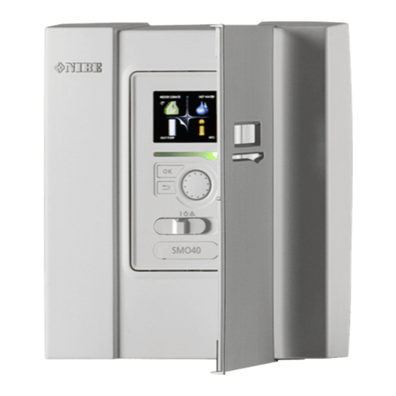
Page 8: The Control Module Design
Terminal block, AUX4 - AUX6 Switch Serial number plate Cable grommet, incoming supply electricity, power for accessories Cable gland, signal Designations in component locations according to standard IEC 81346-1 and 81346-2. Chapter 3 | The Control Module Design SMO 40... -
Page 9: Pipe Connections
General Pipe installation must be carried out in accordance with current norms and directives. See manual for compat- ible NIBE air/water heat pump for installation of the heat pump. Compatible NIBE air/water heat pumps Compatible NIBE air/water heat pumps must be equipped with a control card that has at least the software version given in the following list. -
Page 10: Docking Alternatives
Explanation Docking alternatives AA25 SMO 40 SMO 40 can be connected with other products from Outdoor sensor NIBE in several different ways, some of which are shown Temperature sensor, hot water charging below (accessories may be required). Temperature sensor, hot water top Further option information is available at www.nibe.eu... - Page 11 RN43, RN60 to 63 1) Included in and supplied SMO 40 2) Included in and supplied accessory 3) Included in and supplied NIBE heat pump (can vary depending on heat pump). Designations according to standards 81346-1 and 81346-2. SMO 40...
- Page 12 Compatible NIBE air/water heat pump together with SMO 40 - docking step controlled additional heat before reversing valve for hot water and cooling function (4 pipe system) -AA25 -RN10 -AA25-QN10 -EB1 -EB1 -FL2 -KA1 -BT63 -CM1 -CP10 -AA25-BT7 -AA25 -BT1...
- Page 13 Compatible NIBE air/water heat pump together with SMO 40 - docking step controlled addi- tional heat after reversing valve for hot water and accessory for extra climate system, pool and cooling -EP21 -AA25 -BT2 -GP20 -EB1 -EB1 -BT3 -QN25 -KA1...
- Page 14 Compatible NIBE air/water heat pump together with SMO 40 and electric heater after reversing valve for hot water and pool and extra climate system (floating condensing) -EQ1 -EP22 -EB1 -AA25 -FL10 -AA25 -BT2 -BT64 -CM5 -GP20 -EB1 -BT3 -CP6 -QN25...
-
Page 15: Electrical Connections
If the building is equipped with an earth-fault ■ breaker, SMO 40 should be equipped with a separate one. SMO 40 must be installed via an isolator switch with ■ a minimum breaking gap of 3mm. For the electrical wiring diagram for the control ■... - Page 16 Torx 25 screwdriver. Lift the display unit from its mountings. Align the two lower mountings on the reverse of the display unit with the two upper holes in the panel as illustrated. Chapter 5 | Electrical connections SMO 40...
- Page 17 5. When the electrical connection is ready the display must be reinstalled with three mounting points again, otherwise the front cover cannot be in- stalled. Terminal block 3,5 mm 1 mm 3,5 mm 1 mm SMO 40 Chapter 5 | Electrical connections...
-
Page 18: Connections
20 cm from high voltage cables. EB101-GP12 Power connection AA2-X4 SMO 40 must be installed via an isolator switch with a minimum breaking gap of 3mm. Minimum cable area AA2-X4 must be sized according to the fuse rating used. SMO 40... - Page 19 Connect the heat pump (EB101) with a screened three core cable to terminal block X4:1 (A), X4:2 (B) and X4:3 (GND) on the accessory card (AA5) as illustrated. If several heat pumps are to be connected to SMO 40 these must be connected in cascade as illustrated. NOTE With accessories, up to 8 heat pumps can be controlled by SMO 40.
- Page 20 Temperature sensor, hot water top A temperature sensor for hot water top (BT7) can be connected to SMO 40 to show the water temperature at the top of the tank (if it is possible to install a sensor at the top of the tank).
-
Page 21: Optional Connections
SMO 40 display the sensor must be in- stalled. Connect the room sensor to terminal block X6:3 Connect the cable to terminal X4:1 to 4 where X4:1 is and X6:4 on the input card (AA3). - Page 22 (2 step linear or 3 step binary) can be used SMO 40 controls a shunt valve and start signal to the for step controlled additional heat, which means that additional heating using three relays. If the installation...
- Page 23 NOTE AA2-X4 External accessories are disconnected. Shuttle valve Caution SMO 40 can be supplemented with an external revers- No hot water is produced when emergency ing valve (QN10) for hot water control (see page 55 mode is activated. for accessory).
- Page 24 AUX3 (X6:13-14). On terminal block X2 there are the following selectable inputs AUX4 (X2:1), AUX5 (X2:2) to SMO 40. The alternative is only shown if the cool- andAUX6 (X2:3). Earth for AUX4 to 6 is connected to ing function in the heat pump has been activated.
- Page 25 Contact for activation of “temporary lux" An external switch function can be connected to SMO 40 for activation of the hot water function "temporary lux". The contact must be potential free and connected to the selected input (menu 5.4) on the input card ( AA3) or on terminal block (X2).
- Page 26 X7 at the same time the common alarm is activ- ated (see page 55). Externt External SMO 40 AA3-X7 AA3-X7 The picture shows the relay in the alarm position. Chapter 5 | Electrical connections SMO 40...
-
Page 27: Connecting Accessories
(230V AC). Connecting accessories Instructions for connecting other accessories are in the installation instructions provided. See page 55 for the list of the accessories that can be used with SMO 40. SMO 40 Chapter 5 | Electrical connections... -
Page 28: Commissioning And Adjusting
– "Start-up and inspection". SMO 40 1. Power the heat pump. 2. Power SMO 40. 3. Follow the start guide in the display on SMO 40 alternatively start the start guide in menu 5.7. Commissioning with additional heating only At first start follow the start guide, otherwise follow the list below. -
Page 29: Start Guide
1. Use the control knob to select the help symbol. 2. Press the OK button. The help text often consists of several windows that you can scroll between using the control knob. SMO 40 Chapter 6 | Commissioning and adjusting... -
Page 30: Setting The Cooling/Heating Curve
1. Select the climate system (if more than one) for which the curve is to be changed. 2. When the climate system selection has been con- firmed, the curve number is marked. Chapter 6 | Commissioning and adjusting SMO 40... - Page 31 If it is warm outdoors and the room temperat- ure is too low, increase the curve offset by one increment. If it is warm outdoors and the room temperat- ure is too high, lower the curve offset by one increment. SMO 40 Chapter 6 | Commissioning and adjusting...
-
Page 32: Setting Hot Water Circulation
When the pool temperature drops below the set start temperature and there is no hot water or heating re- quirement, SMO 40 starts pool heating. Untick "activated" to switch off the pool heating. Caution The start temperature cannot be set to a value that is higher than the stop temperature. -
Page 33: Sg Ready
With low price mode on "SG Ready", the desired pool temperature (start and stop temperature) is increased by 1 °C. With over capacity mode of "SG Ready", the desired pool temperature (start and stop temperature) is in- creased by 2 °C. SMO 40 Chapter 6 | Commissioning and adjusting... -
Page 34: Control - Introduction
The control knob can be turned to the right or left. You can: ■ scroll in menus and between options. ■ increase and decrease the values. ■ change page in multiple page instructions (for example help text and service info). Chapter 7 | Control - Introduction SMO 40... -
Page 35: Menu System
This menu only appears if a water heater is installed in setting" is active in 4.7. the system. This symbol indicates whether SMO 40 Menu 3 - INFO has contact with NIBE Uplink™. Display of temperature and other operating informa- tion and access to the alarm log. - Page 36 To select another option: 1. Mark the applicable option. One of the options is pre-selected (white). 2. Press the OK button to confirm the selected option. The selected option has a green tick. Chapter 7 | Control - Introduction SMO 40...
- Page 37 (at the page number) has been marked. 2. Press the OK button to skip between the steps in the start guide. If the start guide is left on this page it closes automatically in 60 min SMO 40 Chapter 7 | Control - Introduction...
-
Page 38: Control
1.9.3.2 - cooling * 1.9.4 - room sensor settings 1.9.5 - cooling settings * 1.9.7 - own curve 1.9.7.1 - heating 1.9.7.2 - cooling * 1.9.8 - point offset * Heat pump with cooling function required. Chapter 8 | Control SMO 40... -
Page 39: Menu 2 - Hot Water
2.9.2 - hot water recirc. * Menu 3 - INFO 3 - INFO 3.1 - service info 3.2 - compressor info 3.3 - add. heat info 3.4 - alarm log 3.5 - indoor temp. log * Accessories are needed. SMO 40 Chapter 8 | Control... -
Page 40: Menu 4 - My System
4 - MY SYSTEM 4.1 - plus functions 4.1.1 - pool * 4.1.2 - pool 2 * 4.1.3 - internet 4.1.3.1 - nibe uplink 4.1.3.8 - tcp/ip settings 4.1.3.9 - proxy settings 4.1.4 - sms * 4.1.5 - SG Ready 4.1.6 - smart price adaption... -
Page 41: Menu 5 - Service
Setting software controlled in and Status information for the relevant menu can be found outputs on the input card (AA3) and terminal block on the display to the right of the menus. (X2). SMO 40 Chapter 8 | Control... - Page 42 2.9.1. The charge method for hot water mode is selected here. "delta temp" is recommended for heaters with charge coil, "target temp" for heaters with domestic coil. Chapter 8 | Control SMO 40...
- Page 43 (only accessible if the additional heat is positioned after QN10), whether binary stepping is to See the accessory installation instructions for be used, the size of the fuse and transformer ratio. function description. SMO 40 Chapter 8 | Control...
- Page 44 This menu is only displayed if SMO 40 is con- nected to a heat pump with inverter controlled Workspace for docking: The system docking is drawn compressor.
- Page 45 External addition with shunt is for If the water heater is connected to SMO 40 hot water example a wood/oil/gas/pellet boiler. charging must be activated here. You can set shunt valve amplification and shunt valve There are two ways of activating connected accessories.
- Page 46 Here you can set the temper- ature in the solar panel at which the circulation pump is to start to prevent freezing. Chapter 8 | Control SMO 40...
- Page 47 Start it manually heater. here. See the accessory installation instructions for function See page 29 for more information about the start description. guide. SMO 40 Chapter 8 | Control...
- Page 48 Set the operating mode for the charge pump here. auto: The charge pump runs according to the current temp. period 1 – 7 operating mode for SMO 40. Setting range: 15 – 70 °C intermittent: The charge pump starts and stops 20...
- Page 49 Select here where the product was installed. This allows access to country specific settings in your product. Language settings can be made regardless of this selec- tion. NOTE This option locks after 24 hours, restart of dis- play or program updating. SMO 40 Chapter 8 | Control...
-
Page 50: Service
(°C) (kOhm) Servicing should only be carried out by persons 351.0 3.256 with the necessary expertise. 251.6 3.240 When replacing components on SMO 40 only 182.5 3.218 replacement parts from NIBE may be used. 133.8 3.189 99.22 3.150 Emergency mode 74.32... - Page 51 (always in English) of the most probable update that the update software has selected form the USB SMO 40 is equipped with a USB socket in the display memory. unit. This USB socket can be used to connect a USB...
- Page 52 Setting range: 1 s – 60 min Factory setting range: 5 s Here you can choose how current measurement values from SMO 40 should be saved onto a log file on the USB memory. 1. Set the desired interval between loggings.
-
Page 53: Disturbances In Comfort
"Holiday mode" activated in menu 4.7. ■ status lamp will therefore continue to be red. Enter menu 4.7 and select "Off". ■ External switch for changing the room heating activ- ■ ated. Check any external switches. ■ SMO 40 Chapter 10 | Disturbances in comfort... -
Page 54: Additional Heating Only
OK button. 3. Return to the main menus by pressing the Back button. Caution When commissioning without NIBE air/water heat pump an alarm communication error may appear in the display. The alarm is reset if the relevant heat pump is deactivated in menu 5.2.2 ("installed slaves"). -
Page 55: Accessories
ELK 15 more than two heat pumps are to be connected to SMO 40. It can also be used for step controlled addi- Immersion heater tional heat (e.g. external electric boiler), shunt con- 15 kW, 3 x 400 V trolled addition (e.g. - Page 56 SMO 40 is located. Part no. 067 064 Solar 40 Solar 40 means that SMO 40 (together with VPAS) can be connected to solar heating. Part no. 067 084 Solar 42 Part no.
-
Page 57: Technical Data
12 Technical data Dimensions and setting-out coordinates SMO 40 Chapter 12 | Technical data... -
Page 58: Technical Specifications
Technical specifications IP 21 SMO 40 Electrical data Supply voltage 230 V ~ 50 Hz Enclosure class IP21 Rated value for impulse voltage Pollution degree Optional connections Max number air/water heat pumps Max number of sensors Max number of charge pumps with internal accessory cards... -
Page 59: Electrical Circuit Diagram
Electrical circuit diagram SMO 40 Chapter 12 | Technical data... - Page 60 Chapter 12 | Technical data SMO 40...
- Page 61 SMO 40 Chapter 12 | Technical data...
- Page 62 Chapter 12 | Technical data SMO 40...
- Page 63 SMO 40 Chapter 12 | Technical data...
- Page 64 Chapter 12 | Technical data SMO 40...
-
Page 65: Index
Power connection, 18 Commissioning and adjusting, 28 Relay output for emergency mode, 23 Commissioning with additional heating only, 28 Reversing valve, 23 Commissioning with NIBE air/water heat pump, 28 Room sensor, 21 Cooling mode, 28 Shunt controlled additional heat, 22 Pool, 32... - Page 66 Temperature sensor, hot water charging, 20 Temperature sensor, hot water top, 20 Temperature sensor, supply line after additional heating, 24 Temperature sensor data, 50 The Control Module Design, 8 Component locations, 8 List of components, 8 Troubleshooting, 53 Chapter 13 | Item register SMO 40...
- Page 68 WS name: -Gemensamt WS version: a89 WS release date: 2015-09-26 11:55 Publish date: 2015-11-13 09:29 NIBE AB Sweden Hannabadsvägen 5 Box 14 SE-285 21 Markaryd info@nibe.se www.nibe.eu 231760...
Need help?
Do you have a question about the SMO 40 and is the answer not in the manual?
Questions and answers