Table of Contents
Advertisement
Quick Links
Bulletin MSG11-5715-718/UK
Operation Manual
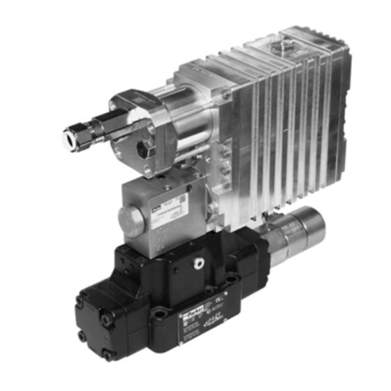
Series D*1F*ED
Design ≥ 10
Pilot Operated
Proportional DC Valve
®
with VCD
-Technology
in Ex-proof Version
Ex II 2G Ex db h IIC T5 Gb
Ambient -20 °C ≤ Ta ≤ +60 °C
Fluid -20 °C ≤ Ta ≤ +60 °C
alternative
Ambient -20 °C ≤ Ta ≤ +50 °C
Fluid -20 °C ≤ Ta ≤ +70 °C
Ex II 2G Ex db h IIC T6 Gb
Ambient -20 °C ≤ Ta ≤ +45 °C
Fluid -20 °C ≤ Ta ≤ +60 °C
alternative
Ambient -20 °C ≤ Ta ≤ +35 °C
Fluid -20 °C ≤ Ta ≤ +70 °C
Parker Hannifin
Manufacturing Germany GmbH & Co. KG
Industrial Systems Division Europe
Gutenbergstr. 38
41564 Kaarst, Germany
Tel.: (+49) 181 99 44 43 0
E-mail: valvesisde@parker.com
Copyright © 2019, Parker Hannifin Corp.
Advertisement
Table of Contents

Related Manuals for Parker D Series


Summary of Contents for Parker D Series
- Page 1 Fluid -20 °C ≤ Ta ≤ +70 °C Parker Hannifin Manufacturing Germany GmbH & Co. KG Industrial Systems Division Europe Gutenbergstr. 38 41564 Kaarst, Germany Tel.: (+49) 181 99 44 43 0 E-mail: valvesisde@parker.com Copyright © 2019, Parker Hannifin Corp.
- Page 2 The user must analyze all aspects of the application, follow applicable industry standards, and follow the information concerning the product in the current product catalog and in any other materials provided from Parker or its subsidiaries or authorized distributors.
-
Page 3: Table Of Contents
ProPxD parameterizing software Air bleeding of hydraulic system Filter Flushing Maintenance Trouble Shooting Accessories / Spare Parts Accessories Spare parts Extract from standards/directives Cable glands Screw plugs EU-Type Examination Certification Certificate of Conformity MSG11-5715-718 D_1FP IECEX UK.indd 19.12.19 Parker Hannifin Corporation... -
Page 4: Ec Declaration Of Conformity
® Pilot Operated Prop. DC Valve with VCD Operation Manual Series D*1FP/FE Explosion Proof 1. EC declaration of conformity MSG11-5715-718 D_1FP IECEX UK.indd 19.12.19 Parker Hannifin Corporation... -
Page 5: Introduction
HFC fluid Code Supply Drain internal external external external internal internal external internal Approx. 10 % opening, only zero lapped spools and underlap spools. Only for overlapped spools. Revision status MSG11-5715-718 D_1FP IECEX UK.indd 19.12.19 Parker Hannifin Corporation... -
Page 6: Ordering Code D*1Fe*Ed
+/- 20 mA 0...+20 mA -> P-B EtherCAT 4...20 mA 12...20 mA -> P-A Code Supply Drain internal external external external Code Seal internal internal external internal for HFC fluid Only for overlapped spools. Revision status MSG11-5715-718 D_1FP IECEX UK.indd 19.12.19 Parker Hannifin Corporation... -
Page 7: Name Plate
• differential input stage with various command signal options • diagnostic output for spool stroke / overcurrent state • meets relevant European EMC-standards Do not connect with supply voltage zero. MSG11-5715-718 D_1FP IECEX UK.indd 19.12.19 Parker Hannifin Corporation... -
Page 8: Pin Adjustment
Provides 24 V signal when no error is detected by the valve electronics, provides 0 V when an error is detected. Reference for diagnostic A8. Reference B11 for command signal A9. Special functions are not shown in the block diagram. MSG11-5715-718 D_1FP IECEX UK.indd 19.12.19 Parker Hannifin Corporation... -
Page 9: Technical Data
Wiring min. [mm²] 8 x 1.0 (AWG16) overall braid shield Wiring length max. [m] 50 Material Electronic housing EN AW 6082 / AlSi1MgMn Valve body EN-GJS-400 / 11SMnPb30+C / 16MnCrS5 / 1.7139/ ESP65 MSG11-5715-718 D_1FP IECEX UK.indd 19.12.19 Parker Hannifin Corporation... -
Page 10: Safety Instructions
Before removing the valve the hydraulic system must be depressurized and power must be disconnected from the electrical installation. MSG11-5715-718 D_1FP IECEX UK.indd 19.12.19 Parker Hannifin Corporation... -
Page 11: Important Details
Do not dismantle the valve. In case of sus- • The valve may be mounted fix or movable in picion for a defect please contact Parker. any direction. Maintenance works carried out by the user Check mounting surface for the valve. -
Page 12: Connector Cap
The Before commissioning the tightening torque requirements according to EN 60079-0: and tightness must be checked. Explosive atmospheres - part 0: General requirements and TRGS 727 have to be observed. MSG11-5715-718 D_1FP IECEX UK.indd 19.12.19 Parker Hannifin Corporation... -
Page 13: Earth Connection
Special gaskets may be available depending on the utilized fluid. a CE-mark. The operating voltage for the In case of insecurity please consult Parker. valve must be free of inductive surges. Do not exceed the max. value of 30 V! Higher The pressure fluid must have an ignition tempera- voltage can lead to failure of the valve. -
Page 14: Mounting Pattern
Pilot Operated Prop. DC Valve with VCD Operation Manual Series D*1FP/FE Explosion Proof Mounting pattern Size 16, mounting pattern ISO 4401-07-07-0-05 Size 25, mounting pattern ISO 4401-08-08-0-05 With * marked dimensions ±0,1 mm. All other dimensions ±0,2 mm. MSG11-5715-718 D_1FP IECEX UK.indd 19.12.19 Parker Hannifin Corporation... - Page 15 ® Pilot Operated Prop. DC Valve with VCD Operation Manual Series D*1FP/FE Explosion Proof Size 32, mounting pattern ISO 4401-10-09-0-05 With * marked dimensions ±0,1 mm. All other dimensions ±0,2 mm. MSG11-5715-718 D_1FP IECEX UK.indd 19.12.19 Parker Hannifin Corporation...
-
Page 16: Operating Instructions
The control electron- ics of the pilot valve compares permanently the transducer signal with the command signal and leads the main spool to its exact position. MSG11-5715-718 D_1FP IECEX UK.indd 19.12.19 Parker Hannifin Corporation... - Page 17 The output may drive a load of max. 5 mA. Exceeding of this limit leads to malfunction. Diagnostic signal 12,5 V in error case. Spool moves in a defined postion, please see ordering code "spool position at power down". MSG11-5715-718 D_1FP IECEX UK.indd 19.12.19 Parker Hannifin Corporation...
-
Page 18: Solenoid Current Monitoring
Parametering interface documentation. The PC software can be downloaded free of charge Screw plug for at www.parker.com/isde – see page “Support” or parametering interface directly at www.parker.com/propxd. Please check periodical for updates. Hardware requirements ®... - Page 19 To prevent an unauthorized access for the expert mode, a password is requested. The name is Brief instruction for first startup: “parker” and cannot be changed. Thus additionally • Connect the valve electronic to the supply voltage. to the button “Default” for loading of the default •...
- Page 20 Only use original IECEx certified screw plug according to EN 60079-1 and tighten with 16 Nm. Before commissioning the tightening torque and tightness must be checked. LED status indication RS232C Interface LED of the valve electronics MSG11-5715-718 D_1FP IECEX UK.indd 19.12.19 Parker Hannifin Corporation...
- Page 21 To turn on resp. off of the cable break detection of the command command signal at a selected command signal option of 4...20 mA. Adjustment of the MIN operating threshold. operating threshold To match the response sensitivity for the MIN-stroke step. MSG11-5715-718 D_1FP IECEX UK.indd 19.12.19 Parker Hannifin Corporation...
- Page 22 Adjustment of the fault response or report: 0 = no fault acknowledgement necessary 255 = fault acknowledgement necessary Errorhandling 768 = no fault acknowledgement + Fault report about diagnosis 1023 = fault acknowledgement + Fault report about diagnosis MSG11-5715-718 D_1FP IECEX UK.indd 19.12.19 Parker Hannifin Corporation...
-
Page 23: Air Bleeding Of Hydraulic System
A detailed required. knowledge is required of how the machine is switched on and off and also of the ne- Pay attention to maintenance details! cessary safety measures. MSG11-5715-718 D_1FP IECEX UK.indd 19.12.19 Parker Hannifin Corporation... -
Page 24: Trouble Shooting
9. Accessories / Spare Parts D41FE SK-D41FE Accessories D81FE SK-D81FE The following accessories are available for the D91FE SK-D91FE valve series D*1FP and D*1FE: D111FE SK-D111FE Mounting bolts see table on page 12. MSG11-5715-718 D_1FP IECEX UK.indd 19.12.19 Parker Hannifin Corporation... -
Page 25: A1 Extract From Standards/Directives
EN 60529:2014 Degrees of protection provided by enclosures (IP code) (IEC 60529:1989 + A1:1999 + A2:2013) TRGS 727 Technical Rule for Hazardous Substances „Avoiding ignition hazards due to electrostatic charges“. Issued January 2016 MSG11-5715-718 D_1FP IECEX UK.indd 19.12.19 Parker Hannifin Corporation... -
Page 26: A2 Cable Glands
® Pilot Operated Prop. DC Valve with VCD Operation Manual Series D*1FP/FE Explosion Proof A2. Cable glands MSG11-5715-718 D_1FP IECEX UK.indd 19.12.19 Parker Hannifin Corporation... - Page 27 ® Pilot Operated Prop. DC Valve with VCD Operation Manual Series D*1FP/FE Explosion Proof MSG11-5715-718 D_1FP IECEX UK.indd 19.12.19 Parker Hannifin Corporation...
-
Page 28: A3 Screw Plugs
® Pilot Operated Prop. DC Valve with VCD Operation Manual Series D*1FP/FE Explosion Proof A3. Screw Plugs MSG11-5715-718 D_1FP IECEX UK.indd 19.12.19 Parker Hannifin Corporation... - Page 29 ® Pilot Operated Prop. DC Valve with VCD Operation Manual Series D*1FP/FE Explosion Proof MSG11-5715-718 D_1FP IECEX UK.indd 19.12.19 Parker Hannifin Corporation...
-
Page 30: A4 Eu-Type Examination Certification
® Pilot Operated Prop. DC Valve with VCD Operation Manual Series D*1FP/FE Explosion Proof A4. EU-Type Examination Certification MSG11-5715-718 D_1FP IECEX UK.indd 19.12.19 Parker Hannifin Corporation... - Page 31 ® Pilot Operated Prop. DC Valve with VCD Operation Manual Series D*1FP/FE Explosion Proof MSG11-5715-718 D_1FP IECEX UK.indd 19.12.19 Parker Hannifin Corporation...
- Page 32 ® Pilot Operated Prop. DC Valve with VCD Operation Manual Series D*1FP/FE Explosion Proof MSG11-5715-718 D_1FP IECEX UK.indd 19.12.19 Parker Hannifin Corporation...
- Page 33 ® Pilot Operated Prop. DC Valve with VCD Operation Manual Series D*1FP/FE Explosion Proof MSG11-5715-718 D_1FP IECEX UK.indd 19.12.19 Parker Hannifin Corporation...
-
Page 34: A5 Certificate Of Conformity
® Pilot Operated Prop. DC Valve with VCD Operation Manual Series D*1FP/FE Explosion Proof A5. Certificate of Conformity MSG11-5715-718 D_1FP IECEX UK.indd 19.12.19 Parker Hannifin Corporation... - Page 35 ® Pilot Operated Prop. DC Valve with VCD Operation Manual Series D*1FP/FE Explosion Proof MSG11-5715-718 D_1FP IECEX UK.indd 19.12.19 Parker Hannifin Corporation...
- Page 36 ® Pilot Operated Prop. DC Valve with VCD Operation Manual Series D*1FP/FE Explosion Proof MSG11-5715-718 D_1FP IECEX UK.indd 19.12.19 Parker Hannifin Corporation...
- Page 37 ® Pilot Operated Prop. DC Valve with VCD Operation Manual Series D*1FP/FE Explosion Proof MSG11-5715-718 D_1FP IECEX UK.indd 19.12.19 Parker Hannifin Corporation...
Need help?
Do you have a question about the D Series and is the answer not in the manual?
Questions and answers