Sign In
Upload
Manuals
Brands
JUMO Manuals
Controller
TYA 202
User Manuals: JUMO TYA 202 Three-Phase Power Controller
Manuals and User Guides for JUMO TYA 202 Three-Phase Power Controller. We have
2
JUMO TYA 202 Three-Phase Power Controller manuals available for free PDF download: Operating Manual
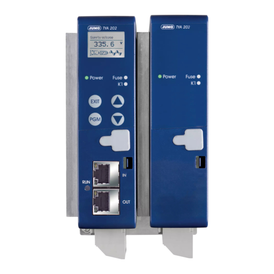
JUMO TYA 202 Operating Manual (120 pages)
TYA 202 series Thyristor power controller in a three-phase economy circuit
Brand:
JUMO
| Category:
Controller
| Size: 5 MB
Table of Contents
Table of Contents
3
1 Introduction
9
Editorial
9
Typographical Conventions
10
Warning Symbols
10
Note Symbols
11
Performing an Action
11
Display Types
11
Order Details
12
Scope of Delivery
13
Accessories
13
General Accessories
13
Brief Description
14
Standards, Approvals, and Conformity
15
2 Mounting
17
Important Installation Notes
17
Environmental Conditions
18
Filtering and Interference Suppression
19
Admissible Load Current Depending on the Ambient Temperature and the Site Altitude
19
Wall Mounting with Screws (Default)
21
Mounting on DIN Rail (Accessories)
24
Dimensions
25
Type 709062/X-0X-020-XXX-XXX-XX-25X
25
Type 709062/X-0X-032-XXX-XXX-XX-25X
26
Type 709062/X-0X-050-XXX-XXX-XX-25X
27
Type 709062/X-0X-100-XXX-XXX-XX-25X
28
Type 709062/X-0X-150-XXX-XXX-XX-25X Type 709062/X-0X-200-XXX-XXX-XX-25X
29
Type 709062/X-0X-250-XXX-XXX-XX-25X
30
Clearances (All Types)
30
3 Electrical Connection
31
Plug-In Screw Terminals with 20 a
31
Type 709062/X-0X-20-XXX-XXX-XX-25X
31
Cable Lugs and Plug-In Screw Terminals as of 32 a
32
Type 709063/X-0X-032-XXX-XXX-XX-25X Type 709063/X-0X-050-XXX-XXX-XX-25X
33
Type 709062/X-0X-100-XXX-XXX-XX-25X
35
Type 709062/X-0X-150-XXX-XXX-XX-25X Type 709062/X-0X-200-XXX-XXX-XX-25X
36
Type 709062/X-0X-250-XXX-XXX-XX-25X
37
Connection Diagram
38
Switch-On Sequence
41
Three-Phase Economic Circuit Master-Slave for Resistive Loads in Star-, Delta Connection or Transformer Loads (Resistive-Induktive)
41
4 Operation
43
Display after Switching on the Device
43
Display and Control Elements
44
Appearance of Measured Values
44
Meaning of the Displayed Measured Values
45
Appearance in the Configuration Level
47
Appearance of Error Messages and Special Statuses
47
Operating Level
48
Device Data
48
Power Controller
49
Setpoint Value Configuration
49
Monitoring
51
5 Configuration
53
Configuration Level
53
Device Data
54
Language Wizard Active
54
Temperature Unit
54
Display Contrast
54
Switch-Off
54
Display Lighting
54
Apply Default Settings
54
Power Controller
54
Thyristor Control
54
Subordinate Control Loop
55
Cycle Time
56
Min. on Period
56
Α Start
56
Α Start Angle
56
Soft Start
56
Soft Start Type
57
Soft Start Duration
57
Current Limiting
57
Current Limit Value
58
Resistance Limitation
58
Resistance Limit Value
58
Dual Energy Management
58
Analog Inputs
59
Current Measuring Range
59
Current Measuring Range, Start
59
Current Measuring Range, End
59
Voltage Measuring Range
59
Voltage Measuring Range, Start
59
Voltage Measuring Range, End
59
Setpoint Value Configuration
60
Setpoint Specification
60
Input in the Event of an Error
60
Value in the Event of an Error
60
Maximum Actuating Variable
60
Base Load
61
Monitoring
62
Limit Value Monitoring
62
Min. Limit Value Alarm
62
Max. Limit Value Alarm
63
Limit Value Hysteresis
63
Load Monitoring
63
Limit Value Load Monitoring
63
Load Type Load Monitoring
63
Teach-In Type Load Monitoring
63
Mains Voltage Drop Monitoring
64
Control Loop Monitoring
64
Digital Inputs
65
External Toggling of Setpoint Specification
65
Setpoint Specification When Toggling
65
Value When Toggling
65
Ext. Current Limiting
65
External Current Limit Value
65
Key Lock
66
External Switch-Off of Display Lighting
66
Inhibit Input Control Direction
66
Control Direction, Digital Input1
66
Control Direction, Digital Input2
66
Digital Output
67
Output Mode
67
Control Direction, Digital Output
68
Analog Output
69
Signal Type, Actual Value Output
69
Value to be Output
69
Signal Range Start Value
69
Signal Range End Value
69
Rs422/485
69
Baud Rate
69
Data Format
69
Device Address
69
Min. Response Time
69
Profibus-Dp
70
Device Address
70
Data Format
70
Ethercat
70
Fieldbus
70
Device ID
70
(Alias-Adr.)
70
Changing Codes
70
Code, Manual Mode
70
Code, Operating Level
70
Configuration Example
71
6 Special Device Functions
73
Detection of Load Faults
73
Teach-In
75
Manual Mode
76
Setpoint Specification in Manual Mode
76
Configuring Teach-In (Prerequisite for Teach-In in Manual Mode)
76
Performing Teach-In in Manual Mode
77
Setpoint Specification Via Potentiometer
78
Dual Energy Management
78
Subordinate Control Loop
81
Closed Control Loop Without Subordinate Control
81
Closed Control Loop with Subordinate Control
82
Resistance Limitation (R-Control)
87
Current Limiting
88
Α Start
88
Monitoring of the Mains Voltage Drop
89
Firing Pulse Inhibit
89
Thyristor Control Logic (Switch)
90
7 Setup Program
91
Hardware
91
Compatible Operating Systems
91
Installation
92
Program Start
94
Forgotten the Code
95
Changing the Language of the Device Texts
96
8 Error Messages and Alarms
97
Binary Signal for Collective Fault
101
Replacing a Defective Semiconductor Fuse
102
Accessories: Semiconductor Fuses
103
Semi-Conductor Fuses Type 709062/X-0X-20
103
Semi-Conductor Fuses Type 709062/X-0X-32
104
9 What to Do, if
107
10 Technical Data
109
Voltage Supply, Fan Specifications for 250A, Load Current
109
Galvanic Isolation
109
Analog Inputs (Master Only)
110
Analog Output (Actual Value Output Master Only)
110
Display and Measuring Accuracy
110
Digital Inputs
110
Digital Output (Fault Signal Output Master Only)
110
General Specifications
111
Approvals / Approval Marks
113
11 Certificates
115
China
117
Advertisement
JUMO TYA 202 Operating Manual (108 pages)
SCR Power Controller in a three-phase economy circuit
Brand:
JUMO
| Category:
Controller
| Size: 7 MB
Table of Contents
Table of Contents
3
1 Introduction
9
Preface
9
Typographical Conventions
10
Warning Signs
10
Note Signs
11
Perform an Action
11
Representation
11
Order Specifications
12
Scope of Delivery
12
Accessories
13
General Accessories
13
Brief Description
14
Standards, Approvals and Conformity
15
2 Installation
17
Important Installation Notes
17
Ambient Conditions
18
Filtering and Interference Suppression
18
Permissible Load Current Depending on the Ambient Temperature
19
Wall Mounting with Screws (Ex Factory)
20
Fixing Onto DIN Rail (Accessories)
23
Dimensions
24
Type 709062/8-0X-020-XXX-XXX-XX-25X
24
Type 709062/8-0X-032-XXX-XXX-XX-25X
25
Type 709062/8-0X-050-XXX-XXX-XX-25X
26
Type 709062/8-0X-100-XXX-XXX-XX-25X
27
Type 709062/8-0X-150-XXX-XXX-XX-25X Type 709062/8-0X-200-XXX-XXX-XX-25X
28
Type 709062/8-0X-250-XXX-XXX-XX-25X
29
Clearances (All Types)
29
3 Electrical Connection
31
Plug-In Screw Terminals
31
Type 709062/8-0X-20-XXX-XXX-XX-25X
31
Cable Lugs and Plug-In Screw Terminals
32
Type 709062/8-0X-032-XXX-XXX-XX-25X
32
Type 709062/8-0X-050-XXX-XXX-XX-25X
33
Type 709062/8-0X-100-XXX-XXX-XX-25X
34
Type 709062/8-0X-150-XXX-XXX-XX-25X Type 709062/8-0X-200-XXX-XXX-XX-25X
35
Type 709062/8-0X-250-XXX-XXX-XX-25X
36
Connection Diagram
37
Three-Phase Economy Circuit, Master/Slave for Resistive Loads in Star, Delta Circuit or Transformer Loads (Resistive-Inductive)
39
4 Operation
41
Display after Switch-On of the Device
41
Display and Control Elements
41
Display of Measured Values
42
Display in the Configuration Level
43
Display of Error Messages and Particular Statuses
44
Operator Level
45
Device Data
45
Power Controller
45
Set Point Value Configuration
46
Monitoring
47
5 Configuration
49
Configuration Level
49
Device Data
50
Temperature Unit
50
Display Contrast
50
Switch off
50
Apply Factory Settings
50
Power Controller
50
SCR Control
50
Cascade Control
51
Cycle Time
52
Min. Duty Cycle
52
A Start
52
Angle a Start
52
Soft Start
52
Type of Soft Start
53
Soft Start Duration
53
Current Limiting
53
Current Limit
53
Resistance Limitation
54
Resistance Limit Value
54
Dual Energy Management
54
Analog Inputs
55
Current Measuring Range
55
Current Measuring Range, Start
55
Current Measuring Range, End
55
Voltage Measuring Range
55
Voltage Measuring Range, Start
55
Voltage Measuring Range, End
55
Set Point Value Configuration
56
Default Set Point Value
56
Default Value in the Event of a Fault
56
Value in the Event of a Fault
56
Maximum Control Variable
56
Base Load
57
Monitoring
58
Limit Value Monitoring
58
Min. Limit Value Alarm
58
Max. Limit Value Alarm
58
Limit Value Hysteresis
58
Load Monitoring
59
Limit Value, Load Monitoring
59
Load Type, Load Monitoring
59
Teach-In Type, Load Monitoring
59
Monitoring of the Supply Voltage Drop
59
Binary Inputs
60
Ext. Current Limiting
60
External Current, Limit Value
60
Key Lock
60
External Display Lighting
60
Control Direction, Inhibit Input
60
Control Direction, Binary Input1
61
Control Direction, Binary Input2
61
Binary Output
62
Control Direction, Binary Output
62
Actual Value Output
63
Signal Type of Actual Value Output
63
Value to be Output
63
Start Value
63
End Value
63
Rs422/485
63
Baud Rate
63
Data Format
63
Device Address
63
Min. Response Time
63
Changing Codes
64
Code Manual Mode
64
Code User Level
64
Code Config.level
64
Profibus-Dp
64
Device Address
64
Data Format
64
Configuration Example
65
6 Special Device Functions
67
Detection of Load Faults
67
Teach-In
69
Manual Mode
70
Default Set Point Value in Manual Mode
70
Configuring the Teach-In (Prerequisite for Teach-In in Manual Mode)
70
Performing Teach-In in Manual Mode
71
Default Set Point Value Via Potentiometer
72
Dual Energy Management
72
Cascade Control
75
Closed Control Loop Without Cascade Control
75
Closed Control Loop with a Subordinate Control
76
Resistance Limitation (R Control)
81
Current Limiting
82
A Start
82
Monitoring of the Supply Voltage Drop
82
Firing-Pulse Inhibit
83
7 Setup Program
85
Hardware and Software, Minimum Requirements
85
Notes for Windows 2000/XP
85
Installation
86
Program Start
88
Forgotten the Code
89
Changing the Language of the Device Texts
90
8 Fault Messages and Alarms
91
Binary Signal for Collective Fault
95
Replace Defective Semi-Conductor Fuse
96
Accessories: Semi-Conductor Fuses
97
Semi-Conductor Fuses Type 709062/8-0X-20
97
Semi-Conductor Fuses Type 709062/8-0X-32
98
9 What to Do if
101
10 Technical Data
103
Voltage Supply, Load Current
103
Electrical Isolation
103
Analog Inputs (Only Master)
104
Analog Output (Actual Value Output, Only Master)
104
Display and Measuring Accuracy
104
Binary Inputs
104
Binary Output (Fault Signal Output, Only Master)
104
General Characteristic Data
105
Advertisement
Related Products
JUMO TYA S201
JUMO TYA S202
Jumo TYA 201
JUMO mTRON T 570
JUMO mTRON T 350
JUMO dTRANS T08 13
JUMO dTRANS T03 TU
JUMO dTRANS T03 B
JUMO dTRANS T03 BU
JUMO tecLine PAA
JUMO Categories
Transmitter
Measuring Instruments
Controller
Thermostat
Voice Recorder
More JUMO Manuals
Login
Sign In
OR
Sign in with Facebook
Sign in with Google
Upload manual
Upload from disk
Upload from URL