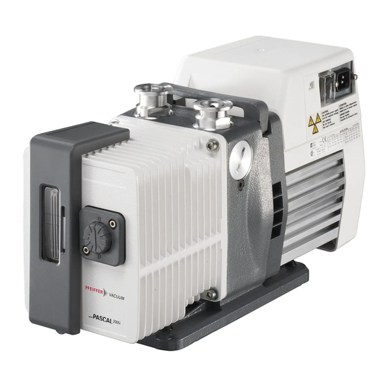
Pfeiffer Vacuum PASCAL Series Maintenance Instructions Manual
Rotary vane pumps 5 to 21 m3/h
Hide thumbs
Also See for PASCAL Series:
- Operating instructions manual (71 pages) ,
- Operating instructions manual (49 pages) ,
- Maintenance instruction (31 pages)

Related Manuals for Pfeiffer Vacuum PASCAL Series


Summary of Contents for Pfeiffer Vacuum PASCAL Series
-
Page 1: Maintenance Instructions
MAINTENANCE INSTRUCTIONS MAINTENANCE INSTRUCTIONS Translation of the original instructions Translation of the original instructions PASCAL SERIES PASCAL SERIES Rotary vane pumps 5 to 21 m Rotary vane pumps 5 to 21 m /h /h... -
Page 2: Table Of Contents
Rotary vane pumps Dear customer, This Maintenance instructions is intended for customers of the Pfeiffer Vacuum Company. It describes the product maintenance operations which can be performed by the user on the product concerned. This documentation must be used together with the operating manual for the product of the same name. - Page 3 MANUAL P/N: 103275M EDITION: 04 - April 2017 Translated from original version Indicates a potentially hazardous situation which, if not avoided, could result in property damage. Indicates a potentially hazardous situation which, if not avoided, could result in moderate or minor injury. It may also be used to alert against unsafe practices.
-
Page 4: Safety Instructions For Maintenance
Vacuum original spare parts, delivered by Pfeiffer Vacuum, containing i.e. all its components and sub-assemblies. This obligation will not cover the shipping cost to a Pfeiffer Vacuum taking back facility. Whenever you return the product to an repair service center, please make sure you follow the Service procedure and fill in the declaration of contamination found on our website. -
Page 5: Tools And Consumable Products
Tools and consumable products Special precautions Read the safety instructions at the beginning of the maintenance chapter. Before disassembling the pump, drain it (see Operating instructions). All the seals and faulty parts should be replaced: provide a seal kit or an overhaul kit. - Page 6 Spare parts (cont’d) Vane kits for 2-stage pumps This kit contains only vanes and springs in order to maintain several pumps of the same model (see table here after). Pumps 2005 2010 2015 2021 LP stage vane kit 108417 108396 108397 108398 Vane / Spring (quantity)
- Page 7 Tools and consumable products (cont’d) Specific tools Tools kit This kit contains the usefull tools to Pump models disassemble and reassemble the shaft All pumps 112397 seals in the different flanges and flanged stators (see table bellow). HP and LP no flanged HP flanged stator LP flanged stator stator (plan D)
-
Page 8: Replacement Of External Shaft Seal
Replacement of external shaft seal In the event of an external oil leak on the pump, it is necessary to change the external shaft seal on the motor side (see page N – 4). You will need: a front seal replacement kit (see page 5), ... -
Page 9: Disassembling The Pump
Disassembling the pump Removing pump from Study the general precautions listed on Maintenance chapter page 3. system The following steps are necessary to protect the pump as far as possible from the effects of corrosion: • Flush pump with a neutral gas (dry nitrogen) during half an hour to prevent toxic or corrosive gases accumulating in the pump. - Page 10 Disassembling Remove the sight glass cover (3). the oil sight glass Remove the plate (1), the ring (4a), the (see page N – 2) sight glass (4) and the O-ring (5). Removing Remove the oil case (6) and its the oil case O-ring (11) after removing the 4 fastening (see page N –...
- Page 11 Disassembling the pump (cont’d) Disassembling the The oil system is set in the factory, it must be reset in the event of SD/SDI pump oil disassembly (see reassembly). However, the system rear flange (4) can be disassembled without (except 1015 SD) modifying the setting.
- Page 12 Disassembling the 1 Insert two screwdrivers in the notches 2 Release the HP rotor (31) from the HP and release the set HP stator (34) and stator (34) and the vanes. pumping module HP rotor (31) in the axis. with flanged stator (see N –...
- Page 13 Disassembling the pump (cont’d) Disassembling the 1 Remove the HP stator (34) by sliding it 2 Insert two screwdrivers in the notches along the HP rotor (31). and release the central plate (29) in the pumping module Remove the HP rotor and the vanes. axis.
-
Page 14: Cleaning Components
Cleaning components Cleaning metal Solvents are required to clean components. components Standard precautions should be taken in compliance with the manufacturer's instructions. After use in mineral or synthetic oil, clean the metal components with a mineral products based solvent such as AXAREL , CARECLEAN , PREMACLEAN NAPHTESOL... -
Page 15: Replacement Of Shaft Seals
Replacement of shaft seals Specific tools • Specific extraction tool. Picture 1 • Specific assembly mandrel. washer • A support plate (or washer). Recommended tools • A flat screwdriver • A hammer. Extracting a shaft • Flange (picture 1): the seal is extracted Picture 2 using a screwdriver, resting on the plate seal from its housing... -
Page 16: Reassembling The Pump
Reassembling the pump Component • All surfaces in contact are coated with oil (rotors, vanes...). • Check that the lubrication holes are not blocked. preparation • Observe the nominal clamping torques for the reassembly of the functional block (see chapter “Nomenclature”). •... - Page 17 Reassembling the pump (cont’d) 1 Fit the front plate (19) on the 2 For not damage the shaft seal, use Reassembling the frame (42). protective sleeve on the rotor axis (or pumping module wrap end of shaft with adhesive tape) with no flanged and oil it.
- Page 18 Reassembling Check that the nozzle is not blocked by sending a jet of compressed air through it. the oil system Spinner-cam, SD and SDI pumps Place the spinner-cam system on the rear plate (4) and fix it with the clips (7). (except 1015 SD) (see page N –...
- Page 19 Reassembling the pump (cont’d) Reassembling (See page 7). the seal-holder (see page N – 2) Reassembling the fan Fit the shaft key (22) (N – 10) on HP rotor. Fit the coupling fan (33) and secure it with the screw (28) and washer (26). and the motor side Fit the drive key on the motor shaft.
-
Page 20: Service
Fill out the «Service Request/Product return» form and send it to your local Pfeiffer in the Pfeiffer Vacuum Service contact. Vacuum Service Include the confirmation on the service request from Pfeiffer Vacuum with your Center shipment. Fill out the declaration of contamination and include it in the shipment (mandatory!). -
Page 21: Nomenclature
Composants de maintenance / Maintenance components / Ersatzteilliste Plan de montage cuve et bâti ..........Oil casing and central housing assembly drawing ....Gesamtplan Ölbehälter und Pumpenträger ........2 / 4 Nomenclature cuve et bâti ..........Oil casing and central housing part list ........Nomenklatur Ölbehälter und Pumpenträger ........3 / 5 Plan du bloc fonctionnel (avec stator non flasqué) (D) ..Pumping module drawing (with no flanged stator) (D) .... - Page 22 Plan de montage cuve et bâti Oil casing and central housing assembly drawing Ölbehälter und Pumpenträger Gesamtplan 1015I 1015I Clamping torque Rep. Part (N·m) Screw FHC M5 x 10 Screw CHC M6 x 25 14 / 20 Screw FHC M6 x 12 12.5 Screw M5 x 16 (s.steel) Screw CHC M6 x 12...
- Page 23 Nomenclature cuve et bâti / Oil casing and central housing part list / Ölbehälter und Pumpenträger Nomenklatur Types/model REF. DÉSIGNATION SPECIFICATION BENENNUNG Bestell. Nr Plaque de niveau Level plate Ölmesstab 106610S Plaque de niveau Level plate Ölmesstab 106609S Vis FHC M5 x 10 Screw FHC M5 x 10 Schraube FHC M5 x 10 Cache de niveau (gris)
- Page 24 Plan de montage cuve et bâti Oil casing and central housing assembly drawing Ölbehälter und Pumpenträger Gesamtplan 1015I 1015I Clamping torque Rep. Part (N·m) Screw FHC M5 x 10 Screw CHC M6 x 25 14 / 20 Screw FHC M6 x 12 12.5 Screw M5 x 16 (s.steel) Screw CHC M6 x 12...
- Page 25 Nomenclature cuve et bâti / Oil casing and central housing part list / Ölbehälter und Pumpenträger Nomenklatur Types/model REF. DÉSIGNATION SPECIFICATION BENENNUNG Bestell. Nr Rondelle d’appui Washer Unterlegscheibe 065847 Joint torique c 2,7 - d 12,1 Bague R1O O-ring c 2.7 - d 12.1 - Ring R1O Dichtung c 2,7 - d 12,1 - Ring R1O Bague épaulée Shouldered ring...
- Page 26 Plan du bloc fonctionnel (avec stator non flasqué) (D) Pumping module drawing (with no flanged stator) (D) Gesamtplan: Funktionsblock mit Stator und Flanschen (D) Clamping torque Rep. Part (N·m) Screw CHC M6 x 30 (s.steel) Screw CHC M6 x 10 (s.steel) Screw CHC M6 x 25 (s.steel)
- Page 27 Nomenclature du bloc fonctionnel Pumping module list Nomenklatur: Funktionsblock mit Stator und Flanschen (D) (avec stator non flasqué) (D) (with no flanged stator) (D) Types/model REF. DÉSIGNATION SPECIFICATION BENENNUNG Bestell. Nr Goupille D6 LG8 Centering pin D6 LG8 Zentrierstift 1/4 1/4 1/4 1/4 1/4 1/4 1/4 1/4 1/4 1/4 1/4 1/4 1/4 1/4 1/4 1/4 Soupape Valve...
- Page 28 Plan du bloc fonctionnel (avec stator non flasqué) (D) Pumping module drawing (with no flanged stator) (D) Gesamtplan: Funktionsblock mit Stator und Flanschen (D) Clamping torque Rep. Part (N·m) Screw CHC M6 x 30 (s.steel) Screw CHC M6 x 10 (s.steel) Screw CHC M6 x 25 (s.steel)
- Page 29 Nomenclature du bloc fonctionnel Pumping module list Nomenklatur: Funktionsblock mit Stator und Flanschen (D) (avec stator non flasqué) (D) (with no flanged stator) (D) Types/model REF. DÉSIGNATION SPECIFICATION BENENNUNG Bestell. Nr Palette BP LP vane Niederdruckschieber Stator BP LP stator Niederdruckstator 103507S Stator BP...
- Page 30 Plan du bloc fonctionnel (avec stator flasqué) (C) Pumping module drawing (with flanged stator) (C) Gesamtplan: Funktionsblock mit Stator-Monoblock (C) Clamping torque Rep. Part (N·m) Screw CHC M6 x 30 (s.steel) Straight fitting M/F 1/4 BSPP 18.0 Screw CHC M6 x 10 (s.steel) Screw CHC M6 x 25 (s.steel) Screw CHC M5 x 8 (s.steel)
- Page 31 Nomenclature du bloc fonctionnel Pumping module list Nomenklatur: Funktionsblock mit (avec stator flasqué) (C) (with flanged stator) (C) Stator-Monoblock (C) Types/model REF. DÉSIGNATION SPECIFICATION BENENNUNG Bestell. Nr Goupille D6 LG8 Centering pin D6 LG8 Zentrierstift 1/4 1/4 1/4 1/5 1/5 1/5 1/5 1/4 1/4 1/4 1/4 1/4 1/4 1/4 1/5 1/5 Soupape Valve...
- Page 32 Plan du bloc fonctionnel (avec stator flasqué) (C) Pumping module drawing (with flanged stator) (C) Gesamtplan: Funktionsblock mit Stator-Monoblock (C) Clamping torque Rep. Part (N·m) Screw CHC M6 x 30 (s.steel) Straight fitting M/F 1/4 BSPP 18.0 Screw CHC M6 x 10 (s.steel) Screw CHC M6 x 25 (s.steel) Screw CHC M5 x 8 (s.steel)
- Page 33 Nomenclature du bloc fonctionnel Pumping module list Nomenklatur: Funktionsblock mit (avec stator flasqué) (C) (with flanged stator) (C) Stator-Monoblock (C) Types/model REF. DÉSIGNATION SPECIFICATION BENENNUNG Bestell. Nr Stator Stator Stator A006466S Stator BP LP stator Niederdruckstator A006037S Stator BP LP stator Niederdruckstator A006038S Stator BP...
- Page 34 Plan du système de lubrification pompe à huile (A) Oil pump system drawing (A) Ölpumpsystem Gesamtplan (A) 1015I Clamping torque Rep. Part (N·m) 16 / 22 Screw CHC M6 x 16 (s.steel) Pin (s.steel) 14.0 Nut HM6 (s.steel)
- Page 35 Nomenclature du système de lubrification pompe à huile / Oil pump system part list / Ölpumpsystem Nomenklatur Types/model REF. DÉSIGNATION SPECIFICATION BENENNUNG Bestell. Nr Couvercle pompe à huile Oil pump cover Ölpumpendeckel 103416 Tube entrée d’air Air admission tube Lufteinlass 104334 Rotor pompe à...
- Page 36 Plan du système de lubrification levier moulinet (B) Oil system drawing (B) Flügenrad-Ölsystem Gesamtplan (B) Clamping torque Rep. Part (N·m) Screw CHC M6 x 16 (s.steel) Screw CHC M6 x 10 (s.steel) Pin (s.steel) 14.0 Nut (s.steel)
- Page 37 Nomenclature du système de lubrification levier moulinet / Oilsystem part list / Flügenrad-Ölsystem Nomenklatur Types/model REF. DÉSIGNATION SPECIFICATION BENENNUNG Bestell. Nr Vis CHC M6 x 16 Screw CHC M6 x 16 Schraube CHC M6 x 16 Rondelle Washer Unterlegscheibe Levier oscillant Equipped lever Hebel Flasque arrière...
- Page 38 Plan ensemble motorisation (M) Motor assembly drawing (M) Motor Gesamtplan (M) Clamping torque Rep. Part (N·m) Screw CHc M6 x 40 (s.steel) Screw Hc M6 x 8.8 (s.steel)
- Page 39 Nomenclature ensemble motorisation (M) / Motor assembly part list (M) / Motor Gesamtheit Nomenklatur (M) MOTEUR UNIVERSEL / UNIVERSAL MOTOR / UNIVERSELLE MOTOR REF. DÉSIGNATION SPECIFICATION BENENNUNG Bestell. Nr Moteur monophasé standard avec interrupteur* Single phase motor with on/off switch* Wechselstrommotor* mit Schalter 108694 Moteur monophasé...
- Page 40 Plan du système bulleur Bubbler system drawing Bubbler system Gesamtplan Nomenclature du système bulleur / Bubbler system part list / Bubbler system Nomenklatur Types/model REF. DÉSIGNATION SPECIFICATION BENENNUNG Bestell. Nr Bouchon 1/8 NPT Plug 1/8 NPT Blindstopfen 1/8 NPT 082926 Manchon Coupling Kupplung...
- Page 41 Remplacement des pièces du bloc fonctionnel non flasqué Pumping module (with no flanged stator) spare parts Pumpenblock (mit Stator und Flanschen) Unterhaltung Teile Modèles 2 étages / 2 stage models / Zweistufige Modelle Bloc fonctionnel / Pumping module / Pumpenblock Modèle non flasqué...
- Page 42 Remplacement des pièces du bloc fonctionnel non flasqué Pumping module (with no flanged stator) spare parts Pumpenblock (mit Stator und Flanschen) Unterhaltung Teile Modèles 2 étages / 2 stage models / Zweistufige Modelle Bloc fonctionnel / Pumping module / Pumpenblock Modèle non flasqué...
- Page 43 Remplacement des pièces, bloc fonctionnel non flasqué Pumping module (with no flanged stator) spare parts Pumpenblock (mit Stator und Flanschen) Unterhaltung Teile Modèles 1 étage / 1 stage models / Einstufige Modelle Bloc fonctionnel / Pumping module / Pumpenblock Modèle non flasqué...
- Page 44 VACUUM SOLUTIONS FROM A SINGLE SOURCE VACUUM SOLUTIONS FROM A SINGLE SOURCE Pfeiffer Vacuum stands for innovative and custom vacuum solutions worldwide, Pfeiffer Vacuum stands for innovative and custom vacuum solutions worldwide, technological perfection, competent advice and reliable service. technological perfection, competent advice and reliable service.
Need help?
Do you have a question about the PASCAL Series and is the answer not in the manual?
Questions and answers